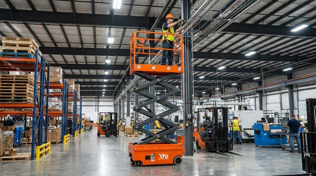
Scissor lifts are highly stable when engineers keep the center of gravity inside a wide support base and operators respect load, wind, and ground limits. This guide explains how stable are scissor lifts in real jobs, from design physics to on-site practices.
You will see how base width, platform size, and mass layout work together with sensors, hydraulics, and automatic leveling to prevent tip-overs. We then connect that engineering to load charts, wind limits, ground assessment, and training so you can specify and operate scissor platform lifts with a solid stability margin instead of guesswork.
How Scissor Lifts Achieve Intrinsic Stability
Scissor lifts achieve intrinsic stability by keeping the combined center of gravity inside a wide support polygon and directing loads straight down into the chassis. Understanding this geometry answers the question “how stable are scissor lifts” under real job‑site conditions.
Engineers tune base width, platform size, mass layout, and load paths so the machine resists tipping even at full height and near rated capacity. When operators then respect capacity and ground limits, modern units offer a high stability margin for work at height.
Support polygon, base width, and platform size
The support polygon, base width, and platform size define the geometric “footprint” that makes scissor lifts inherently stable when used within their design envelope.
The support polygon is the area enclosed by the wheels or outriggers. As long as the combined center of gravity (CG) of machine plus load stays inside this polygon, the lift resists tipping. A wider base and longer wheelbase push the tipping axes further from the CG, increasing the overturning moment required to cause a tip-over. A larger platform footprint then helps spread the load so the CG stays centered over the chassis.
| Design Element | Engineering Role | Typical Design Effect | Operational Impact |
|---|---|---|---|
| Base width | Sets lateral tipping axis distance from CG | Wider base significantly reduces tipping risk at maximum height or under heavy loads by increasing CG distance to the tipping edge | Improves side-to-side stability in narrow aisles and when the platform is fully raised. |
| Wheelbase (length) | Sets longitudinal tipping axis distance | Longer wheelbase increases resistance to tipping forward or backward when driving or braking | Helps when traveling on gentle slopes or stopping quickly with tools on board. |
| Platform length | Defines front–rear load spread | Larger platforms distribute worker and material weight more evenly across the structure | Allows two workers plus materials without concentrating load at one end. |
| Platform width | Defines side-to-side load spread | Wider platforms give operators room to work while keeping weight inside the support polygon | Reduces need to lean out, which cuts both fall and tipping risk. |
| Support polygon area | Overall tipping resistance envelope | Larger polygon means more margin before the CG crosses a tipping edge under rated loads | Directly answers “how stable are scissor lifts” for a given model and load case. |
From a physics perspective, stability is a lever-arm problem. Increasing base width and wheelbase increases the lever arm of the resisting moment, so the same side load (from wind or a worker shifting) produces a smaller rotation angle. That is why compact indoor units often trade some base width for maneuverability, while rough-terrain models accept a wider footprint for more stability on uneven ground.
- Wide base: Increases overturning resistance – Gives more margin against side loads at full height.
- Generous platform area: Spreads weight over the chassis – Keeps CG near the center when multiple workers are on deck.
- Respecting platform limits: Avoids edge and point loading – Prevents one corner from seeing double the stress of a centered load.
How the support polygon limits feel to an operator
When you walk to the guardrail with tools, you move the CG toward one edge of the support polygon. If the machine is narrow, the CG shift is proportionally larger relative to base width. This is why manufacturers restrict leaning, climbing guardrails, or stacking materials at one end, even when total weight is below the stated capacity.
💡 Field Engineer’s Note: On tight indoor jobs, planners often focus on getting through 900–1,000 mm doorways and forget stability. If you choose the narrowest unit that fits the door, compensate by keeping loads centered, avoiding edge loading, and never elevating on anything but a truly level slab; narrow bases leave far less margin for sloppy loading.
Center of gravity, mass layout, and load paths
The center of gravity, mass layout, and load paths explain why a scissor lift stays upright even when the platform moves, people walk, and wind pushes on the structure.
Engineers position heavy components—batteries, engines, hydraulic power units—low in the chassis to keep the overall CG height down. A low CG means lateral forces must generate a larger overturning moment to reach the tipping edge. Concentrating mass near the base also reduces sway because the “pendulum” length from CG to ground is shorter. This is a key part of how stable scissor lifts feel in real use.
- Low-mounted heavy components: Batteries and power packs sit near floor level – Reduce CG height and improve stability on minor unevenness.
- Central mass layout: Heavy parts cluster near the geometric center – Keeps the CG inside the support polygon even as the platform moves.
- Vertical load paths: Scissor arms, pins, and chassis align under the platform – Ensure loads travel straight down, not diagonally into one corner.
Good CG management is not only about static balance; it also controls dynamic behavior. When workers walk across the platform or materials shift, the CG moves. A low, centrally located CG reduces the angular acceleration from these shifts, so the platform feels controlled rather than “tippy.” Engineers analyze these effects and route load paths to keep forces within structural members.
| Stability Factor | Engineering Approach | Effect on “How Stable Are Scissor Lifts” | Best For… |
|---|---|---|---|
| Overall CG height | Place heavy components low in the chassis to reduce CG height | Improves resistance to tipping on uneven or sloped ground and under wind loads. | Indoor slabs with minor floor irregularities and outdoor hardstands with small gradients. |
| Mass distribution | Cluster heavy items centrally along both length and width | Keeps CG near geometric center so typical platform movements do not cross tipping edges. | Jobs with frequent repositioning and worker movement. |
| Load paths | Align scissor arms and pins so vertical loads remain centered through the chassis under rated loading | Prevents one side of the structure from carrying disproportionate stress. | Repeated up/down cycles with near-SWL loads across long shifts. |
| Load distribution on platform | Encourage even spread of workers and materials across the deck to keep CG within footprint | Even loads directly support stability; uneven loads increase tipping risk. | Two-person tasks with tools, pipe, or duct sections on the platform. |
Edge loading is a good example of how CG and load paths interact. When the same weight sits near one platform edge, the supporting bearings and structure at that edge can see about double the force compared with a centered load, even though total mass is unchanged due to shifted load paths. This reduces the safety margin and makes the system more sensitive to additional disturbances like wind or sudden worker movement.
- Step 1: Place heavy materials near platform center – This keeps the CG aligned over the strongest part of the structure.
- Step 2: Space workers along the length, not both at one end – Balances the CG so no single edge is overloaded.
- Step 3: Avoid stacking on guardrails or toe boards – Prevents the CG from migrating toward the tipping axis.
- Step 4: Re-check load when extending deck sections – Deck extensions change the CG lever arm and can increase overturning moment.
How engineers check CG and stability in design
Designers model the lift at multiple heights and load positions. They ensure that, for all rated load distributions (full surface, half-length, half-width), the combined CG remains well inside the support polygon with a safety factor. They also run load path analyses to confirm that no pin, arm, or weldment exceeds allowable stress under these CG positions.
💡 Field Engineer’s Note: On real sites, the biggest CG problem is not the machine; it is long or bulky materials. If you stand a 3–4 m sheet or duct section upright against the guardrail, you create a high, offset “sail” that shifts both CG and wind load to one edge—this is where nominally “stable” scissor lifts suddenly feel unsafe, even when the scale says you are under capacity.
Key Stability Technologies And Load Management
This section explains how modern stability technologies and load management practices keep scissor lifts stable, so you can confidently answer “how stable are scissor lifts” for real jobs and real sites.
Load charts, SWL, and capacity versus height
Load charts, Safe Working Load (SWL), and capacity-versus-height curves define exactly how stable scissor platform lift remain across their working envelope when correctly loaded and used.
Engineers prove stability by testing against structured load cases and then derating for wear, dynamics, and unknowns. Operators see the result as simple numbers on the data plate and load chart, but behind that sit strict factors of safety and standards.
| Concept | Typical Engineering Rule | Operational Impact |
|---|---|---|
| Rated Load | Maximum platform load under defined test conditions | Number printed on the machine; never exceed it during use |
| Safe Working Load (SWL) | Often ≈75% of maximum structural capacity Source | Builds in margin for dynamic forces and wear; use this as your real-world limit |
| OSHA Structural Factor | Structure must support ≥4× rated load without failure Source | Shows how stable scissor lifts are when correctly used; large hidden safety reserve |
| Standards Envelope | OSHA, EN 1570-1, ANSI / ISO govern load, distribution, and testing Source | Ensures comparable stability expectations across models and regions |
Capacity also changes with height because overturning moments grow as the platform rises. Engineers balance base width, mass layout, and cylinder forces so the combined centre of gravity stays inside the support polygon across the whole stroke.
| Working Height (approx.) | Typical Rated Capacity | Best For… |
|---|---|---|
| 8 m | ≈230 kg Source | 1–2 technicians plus light tools indoors |
| 10 m | ≈250–450 kg Source | Two workers plus moderate materials |
| 14 m | ≈320 kg (electric compact units) Source | Height-focused work with controlled payloads |
| 15–18 m | ≈750 kg (high-capacity units) Source | Heavy materials handling at large outdoor heights |
- Rule: Always read the chart on that exact lift: Charts reflect that machine’s geometry and options – assumptions from another model can be unsafe.
- Rule: Treat SWL as your hard ceiling: The extra structural factor is for unknowns – not permission to overload.
- Rule: Respect height derating: If the chart shows lower kg at higher m – reduce people or materials accordingly.
How engineers convert charts into stability margins
Engineers use stability ratios like S = (W × CG) / (F × L), checking that the overturning moment from load and wind remains well below the restoring moment from the machine’s weight and base width across the whole height range Source. This is one of the reasons how stable are scissor lifts when operated within their charts.
💡 Field Engineer’s Note: If you cannot see or read the load chart at ground level due to dirt, fading, or damage, tag the lift out. In practice, most overload-related incidents I investigated started with “we assumed it could carry what the last lift did.”
Load distribution, edge loading, and dynamic effects
Load distribution, edge loading, and dynamic effects explain why a “within the limit” load can still compromise how stable aerial platform are if it is in the wrong place or moving.
The platform and scissor pack are designed for specified patterns: full-surface load, half-length load, half-width load, and sometimes defined point loads. Stability and structural stress both change when you push outside those patterns.
| Load Case | Engineering Requirement | Operational Impact |
|---|---|---|
| Full-surface load | Platform must support 100% of rated load evenly spread Source | Use this pattern whenever possible for best stability margin |
| Half platform length | Lift must safely handle ≥50% of nominal capacity Source | Keep heavy materials near the centre, not bunched at one end |
| Half platform width | Must carry ≈33% of nominal capacity Source | Avoid stacking weight along one side rail |
| Edge loading | Edge loads can roughly double bearing forces versus centred load Source | Same kg can be unsafe if pushed against one edge or corner |
Dynamic effects further erode stability margins. Sudden braking, turning at height, or swinging long materials can shift the combined centre of gravity towards the tipping line faster than the structure and tyres can react.
- Even spread: Keep people and tools distributed across the deck – this keeps the centre of gravity inside the base footprint.
- Avoid edge stacks: Do not lean pallets, sheet packs, or ducting against guardrails – this magnifies edge loading and sway.
- Control motion: Use slow travel and gentle control inputs at height – this limits dynamic amplifiers on the structure.
- Secure long items: Align pipes, beams, and boards with the long axis and tie them down – this prevents sudden shifts from wind or bumps.
Practical checklist before lifting materials
Ask four questions: Is total kg below SWL? Is the load centred in both length and width? Are long items aligned with the platform and secured? Will I move or drive with this load at height? If any answer is “no” or “not sure,” re-stack or reduce the load.
💡 Field Engineer’s Note: Most “mystery” tip-overs I reviewed were not pure overloads; they were edge-loaded toolboxes, stacked drywall, or workers crowding one rail to reach. The platform looked half empty, but the bearings and structure saw nearly double the design force at one side.
Sensors, hydraulics, and automatic leveling systems
Sensors, hydraulic controls, and automatic leveling systems actively manage risk in real time, turning a static scissor structure into a smart system that protects stability even when operators make mistakes.
These technologies constantly measure tilt, load, and hydraulic pressure, then limit movement or trigger alarms before the machine reaches an unsafe state. This is a major reason how stable hydraulic pallet truck are today compared with older generations.
| Technology | Function | Stability Benefit |
|---|---|---|
| Tilt sensors / inclinometers | Measure chassis angle; alarm or lock-out beyond set degrees Source | Prevents elevation on slopes that would move CG near tipping line |
| Load sensing | Monitors total and distributed platform weight Source | Stops lift/drive when overload or severe off-centre loading is detected |
| Hydraulic relief valves | Limit maximum pressure in cylinders and hoses Source | Prevents structural overload and jerky motion from pressure spikes |
| Flow controllers | Control lift and lower speed Source | Gives smooth motion, reducing dynamic rocking and operator over-correction |
| Automatic leveling systems | Use stabilizers or outriggers to keep the chassis level on uneven ground Auto-level systems | Maintains vertical load path through scissor stack, enhancing stability on slopes |
- Tilt interlocks: If the chassis exceeds the allowed angle, elevation stops – you may still drive down to a safe area, but not go higher.
- Load alarms: Overload or severe off-centre loads will trigger a buzzer and lock out further elevation – you must remove weight or re-stack.
- Auto-level: On rough terrain models, stabilizers automatically adjust until the frame is within a small degree window – you start work with the CG correctly positioned.
- Predictive and remote monitoring: Telematics track slope use, overload events, and hydraulic temperatures – fleets can pull problem units before a failure occurs.
Hydraulics, cold weather, and stability
Cold environments increase oil viscosity, which slows response and can cause uneven cylinder speeds. Good practice is to use oil grades suited to the temperature band and to warm up the system with low, no-load cycles before going to full height Source. This keeps motion predictable and reduces sudden
Operator Practices, Site Conditions, And Risk Controls
Operator practice and site conditions ultimately decide how stable scissor lifts are in real jobs, even when the machine’s design is sound. If you want a confident answer to “how stable are scissor lifts,” the honest reply is: they are very stable within their rated envelope, but only when operators respect ground limits, slope ratings, wind limits, and load rules, and when supervisors enforce disciplined inspections and traffic control. The following two subsections translate that into concrete, field-ready controls.
💡 Field Engineer’s Note: When a scissor lift tips in the real world, we almost always find a site condition problem—soft ground, hidden voids, or ignored wind limits—rather than a structural design failure. Treat the ground and weather as part of the lifting system, not background noise.
Ground conditions, slopes, and site assessment
Ground quality and slope control are the first stability barrier, because the support polygon is only as good as the soil or slab under the wheels. Even a perfectly designed lift can overturn if one wheel sinks into a soft spot or the chassis sits beyond its rated tilt angle.
Scissor lifts should sit on firm, level ground free from voids, trenches, soft spots, or debris that could crush or shift under wheel loads. On marginal surfaces such as compacted fill or asphalt in hot weather, supervisors should confirm bearing capacity and use suitable mats or plates to spread the load so the contact pressure stays below the soil’s safe bearing value. Engineering guidance emphasizes firm, compacted support and avoidance of voids or trenches. A structured site assessment process should evaluate soil bearing capacity, surface stiffness, and slope before positioning a scissor platform, comparing expected ground contact pressure with documented soil bearing values and applying a conservative safety factor of at least 2.0 to account for variability. This type of assessment is standard good practice for aerial work platforms.
Manufacturers specify maximum longitudinal and lateral slope ratings for both driving and elevating, and exceeding these ratings sharply increases tip-over likelihood because the combined center of gravity moves toward the downhill edge of the support polygon. Safe practice includes traveling straight up or down slopes with the designated counterweight or heavy end facing uphill to maintain a favorable center of gravity and avoiding cross-slope travel where possible. Guidance on operating on slopes highlights the importance of respecting these manufacturer ratings. Operators should position scissor lifts only on firm, level, and compacted ground, avoiding soft soils, voids, and trenches, and before elevation they must verify that the chassis sits level within the manufacturer’s allowable slope tolerance, typically less than about 3° for indoor units. Technical operation guides consistently stress firm, level support and strict slope control. In simple terms, if you want to keep scissor lifts stable, you treat ground and slope checks as non-negotiable steps before anyone leaves the ground.
- Firm, level support: Use only compacted, stiff ground or engineered slabs – prevents one wheel sinking and collapsing the support polygon.
- Void and trench avoidance: Stay clear of manholes, backfilled trenches, and underground services – reduces risk of sudden local ground failure.
- Bearing capacity checks: Compare wheel loads to soil data with ≥2.0 safety factor – keeps contact pressure within what the soil can safely carry.
- Load-spreading mats: Use steel plates or mats on marginal soils – spreads forces and stabilizes the support area.
- Respect slope ratings: Never drive or elevate beyond rated longitudinal/lateral tilt – keeps the center of gravity inside the support polygon.
- Travel orientation on slopes: Move straight up/down with heavy end uphill – maintains a stable center of gravity position.
- Pre-use ground check: Walk the route and work area before positioning – catches soft patches and hazards the operator might miss from the platform.
How to think about wheel loads and soil in simple terms
For a compact electric scissor lift weighing roughly 2,500 kg with a 300 kg load, total mass is about 2,800 kg. If that sits on four wheels, each wheel may see around 700 kg, more when braking or on slopes. On soft clay or poorly compacted fill, that load can exceed the soil’s safe bearing capacity, especially near edges or trenches, which is why plates or mats and a 2.0+ safety factor are recommended before you elevate.
Wind, weather, and environmental limitations
Wind and weather conditions are the second major external factor controlling how stable scissor lifts are, because they add horizontal loads, reduce friction, and change how the structure and ground behave. Most overturns in otherwise “flat and solid” areas involve wind, sheeting materials acting as sails, or weather-softened soil.
Safe operation is typically limited to wind speeds below about 12.5 m/s (approximately 28 mph); above this, overturning risk increases sharply as the wind moment about the base approaches the resisting moment from the machine’s weight and base width. Operators should check both steady wind and gust forecasts, avoid using tarps or large sheet materials as “sails,” and lower the platform immediately if conditions worsen. Wind limits around 28 mph are widely cited for safe scissor lift operation. Outdoor scissor lift use depends on weather conditions meeting manufacturer limits, and operators should check wind speed with calibrated anemometers and respect the specified maximum; operations should stop during thunderstorms, heavy rain, icing, or poor visibility because these conditions combine reduced friction, higher dynamic loads, and impaired operator judgment. Operational best practices highlight wind speed checks and strict weather limits.
Rain reduces tire-ground friction and softens unpaved soils, cold environments affect hydraulic oil viscosity and battery capacity, and high heat introduces constraints like heat stress for operators and accelerated wear on batteries and electronics. Engineering analyses of weather effects on scissor lifts emphasize these mechanisms. Outdoor operation also requires robust protection of electrical and hydraulic subsystems, with enclosures, cable glands, and connectors using ingress protection ratings consistent with the expected environment, typically at least IP54 for splashing water, and hydraulic circuits protected from contamination, impact, and temperature extremes. Proper environmental protection keeps control and stability systems reliable in harsh conditions. When you combine these controls—wind limits, weather checks, and environmental hardening—aerial platform remains predictably stable within their rated wind and height envelope.
| Environmental Factor | Typical Limit / Effect | Operational Impact on Stability |
|---|---|---|
| Wind speed | Max around 12.5 m/s (≈28 mph) for outdoor use | Above this, overturning moment rises sharply; stop work and lower platform. |
| Gusts vs steady wind | Short gusts can exceed average by 30–50% | Sudden extra side load can tip a marginally stable lift; use conservative limits. |
| Rain | Reduces friction and softens unpaved ground | Higher slip risk and wheel sinkage; re-check ground and reduce travel speed. |
| Cold (≈0°C and below) | Higher oil viscosity, lower battery capacity | Sluggish hydraulics and reduced duty cycle; avoid jerky control inputs. |
| High heat (>30–35°C) | Operator heat stress, battery/electronic derating | Fatigue and slower reactions; plan shorter shifts and extra checks. |
| Snow/ice | Very low surface friction, hidden soft spots | Severe slip and sink risk; generally unsuitable without engineered controls. |
- Measure, don’t guess wind: Use an anemometer at platform or roof level – prevents underestimating wind at height.
- Respect wind ratings: Stop and lower the lift if wind nears the limit – keeps overturning moments within design assumptions.
- Avoid “sail” materials: Control tarps, panels, and sheet goods – prevents sudden side loads from gusts.
- Weather-based go/no-go: Define clear rules for rain, storms, and poor visibility – removes subjective decisions under pressure.
- Check ground after rain: Re-verify soil firmness and bearing capacity – accounts for softened or eroded surfaces.
- Protect systems (IP rating): Use enclosures and connectors with at least IP54 outdoors – keeps controls and sensors reliable.
- Temperature-aware operation: Adjust duty cycles in very hot or cold conditions – reduces stress on hydraulics and batteries.
Why 28 mph (≈12.5 m/s) is a common wind limit
The 12.5 m/s (≈28 mph) limit balances typical platform area, height, and machine weight so the wind-induced overturning moment stays below the restoring moment with a safety margin. Above this range, small increases in wind speed produce disproportionately larger forces on the guardrails, occupants, and any materials, quickly eroding that margin. This is why both engineering guidance and safety regulators converge around similar wind thresholds for mobile elevating work platforms.
“”
Final Thoughts On Specifying And Operating Stable Scissor Lifts
Scissor lift stability does not come from one feature. It comes from geometry, load control, and disciplined operation working together. Engineers create a wide, stiff support polygon, keep the center of gravity low and central, and route loads straight down through the scissor stack. Sensors, hydraulics, and automatic leveling then watch tilt, weight, and motion and step in when conditions drift toward unsafe.
On site, teams either protect that engineered stability margin or destroy it. Poor ground, ignored slope limits, edge loading, and wind “sails” can move the center of gravity toward the tipping line long before you exceed rated load. Good practice keeps loads centered, uses charts for that exact lift, measures wind, and treats ground checks as part of the lifting system, not an optional extra.
For engineering and operations leaders, the best approach is simple. Choose scissor lifts whose base width, capacity, and wind rating match the real job, not the ideal one. Build standard procedures for ground assessment, weather limits, and load layout. Train operators to trust interlocks and stop when alarms trigger. When you combine sound design with strict field controls, Atomoving scissor platforms deliver predictable, repeatable stability across their full working envelope.
Frequently Asked Questions
How stable are scissor lifts?
Scissor lifts are designed with a wide base and an “X”-shaped crisscross mechanism that provides vertical elevation. This design makes them highly stable, especially on flat and even surfaces. They feature larger platforms that can support multiple workers and tools, making them ideal for indoor use. However, stability can be compromised if the lift is overloaded or used in adverse conditions like strong winds Scissor Lift Safety Tips.
- Always operate on flat, level surfaces.
- Avoid using in wind speeds over 25 mph.
- Never exceed the manufacturer’s load capacity.
What factors affect the stability of a scissor lift?
Several factors can impact the stability of a scissor lift. Overloading is one of the most common issues, as exceeding the weight limit can strain the machinery and lead to instability or collapse. Environmental conditions such as high winds can also cause wobbling or loss of balance. Proper training and adherence to operational guidelines are essential to maintaining stability Avoid Scissor Lift Mistakes.
- Check and adhere to load capacity limits.
- Ensure the ground is firm, flat, and level before operation.
- Be mindful of weather conditions, particularly wind speed.

