Scissor lift stability depends on a tight interaction between engineering design, safety systems, and day‑to‑day operating practice. This article explains how base width, platform geometry, center of gravity, hydraulics, and sensors work together to keep the platform upright and controllable. You will also see how regulations, wind limits, load planning, and ground assessment affect real‑world safety on site. Use these principles to specify, operate, and maintain scissor platform lifts with a clear margin of stability for your application.
What Determines Scissor Lift Stability?
Core stability concepts and definitions
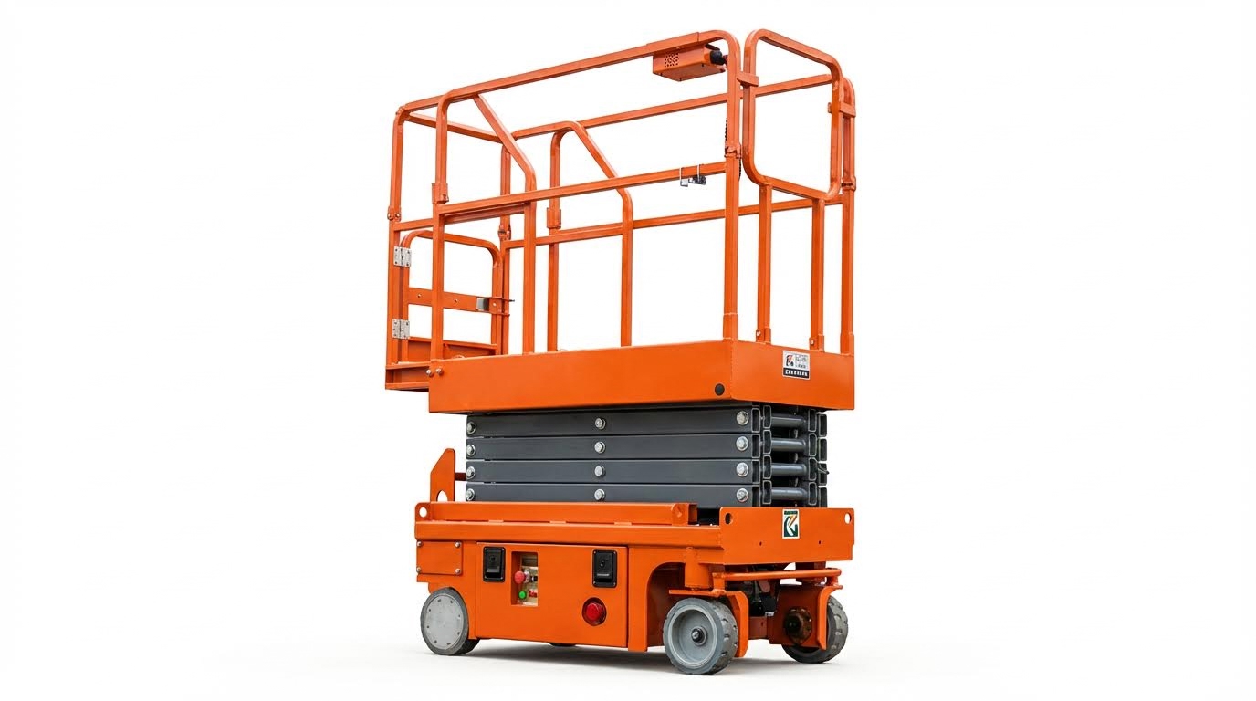
Scissor lift stability is the ability of the machine to resist tipping, sliding, or collapsing while raising, lowering, or driving with a load. In engineering terms, a lift is stable when its combined center of gravity (machine plus load) stays inside the support polygon formed by the wheels or outriggers throughout the full operating envelope. Base width, platform size, and the vertical position of the center of gravity are key geometric drivers of scissor platform stability, because they set the tipping margins under wind, braking, and worker movement loads. A wider base and larger platform footprint significantly reduce tipping risks at maximum height or under heavy loads by spreading forces over a larger support area and improving resistance to overturning moments. Proper weight distribution keeps the center of gravity aligned within that footprint, so the lift remains stable even when multiple workers and bulky materials are on the platform and moving during tasks. Designers improve scissor lift stability further by concentrating heavy components, such as batteries and hydraulic power packs, low in the chassis to reduce the center-of-gravity height and limit the effect of uneven or sloped ground on tip-over risk. Modern hydraulic circuits, tilt sensors, and load-sensing systems support the mechanical design by smoothing motion and stopping unsafe operations, but they do not replace the need for correct geometry and conservative loading practices.
Regulatory standards and design envelopes
Regulatory standards define the minimum stability performance that scissor lifts must achieve before they enter the market. These rules set test conditions for overturning, structural strength, guardrail design, and safe operating envelopes, so that a compliant lift can tolerate defined wind, slope, and load combinations without tipping. For example, guidance for outdoor-rated scissor lifts typically limits operation to wind speeds below about 28 miles per hour; exceeding this threshold has led to past fatal incidents when gusts over 50 miles per hour destabilized elevated platforms and caused tip-overs. Standards also require that the rated load on the work platform must not be exceeded, because overloading or poor load placement can move the center of gravity outside the base and defeat the designed stability margins even if the machine itself is structurally sound. Within the design envelope, manufacturers specify maximum platform height, allowable side forces, and any slope or wind limits that preserve scissor platform lift stability under worst-case test conditions. Operators are expected to stay inside this published envelope, use the lift only on firm, level ground, and follow inspection and training requirements so that real-world use matches the assumptions built into the standards and stability calculations for safe operation.
Engineering Factors That Control Stability
Base width, platform size, and height ratios
From a design perspective, scissor platform stability starts with the geometry of the base and platform. A wider base reduces tipping risk at full elevation or under heavy load because it increases the distance between the center of gravity and the tipping axis, giving a larger restoring moment against side loads such as wind or worker movement. A larger platform can improve stability by spreading the imposed load over a greater area of the chassis, but only when total load and reach stay within the rated design envelope. Wider bases and larger decks work together to keep the combined center of gravity well inside the footprint during travel and elevation, which is critical for safe outdoor and indoor use. In practice, engineers evaluate base‑to‑height ratios and platform dimensions so that, at maximum rated height and capacity, the overturning moment from worst‑case loading and wind remains lower than the resisting moment from the machine’s weight and footprint, with an appropriate safety factor.
- A wider base significantly reduces tipping risk at maximum height or under heavy loads. Wider bases improve resistance to side forces.
- Larger platforms help distribute weight more evenly, which supports scissor platform lift stability when multiple workers and tools are on deck. Platform size directly influences weight spread.
- Designers must balance platform area with rated capacity, since larger decks that are overloaded quickly increase instability risk.
Why ratios matter more than single dimensions
The same platform size behaves very differently on a short, wide base versus a tall, narrow one. Engineers therefore work with non-dimensional ratios (height/base width, load/footprint, etc.) to ensure a consistent stability margin across different models and working heights.
Center of gravity, mass layout, and load paths
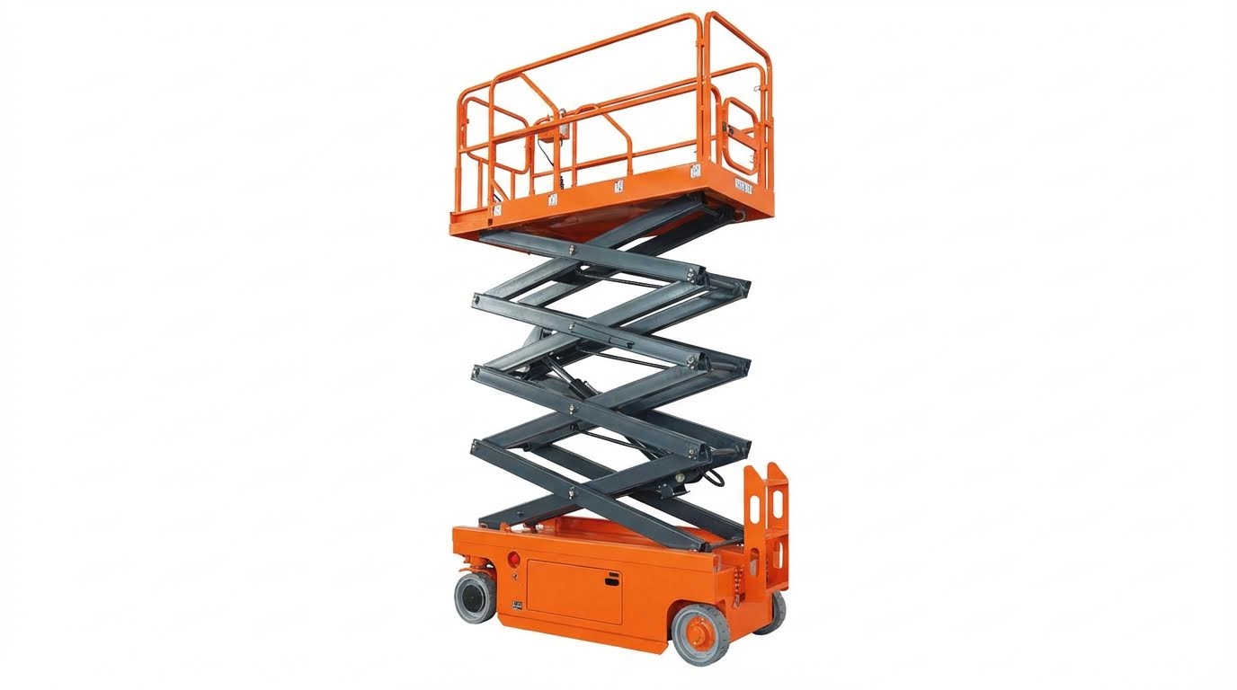
Beyond footprint geometry, aerial platform stability depends strongly on how mass is placed and how loads flow through the structure. Positioning heavy components such as batteries and hydraulic power units low in the chassis reduces the overall center of gravity height and improves resistance to tipping, especially on uneven or sloped ground. Concentrating mass near the base also reduces dynamic sway because the structure behaves more like an inverted pendulum with a shorter effective length. Engineers analyze load paths through the scissor arms, pins, and chassis so vertical loads remain centered and do not create unexpected torsion or side loads that could compromise stability.
- Locating heavy components near the base lowers the center of gravity and helps maintain stability on slopes and rough terrain. Lower mass concentration at the base is a key design choice.
- Safe operation requires the combined center of gravity of machine plus load to remain within the base footprint throughout the full lift range. Proper weight distribution keeps the center of gravity inside the footprint.
- Simple engineering formulas help estimate load distribution and center of gravity location for custom attachments or atypical loads. For example, total load on the scissor legs can be approximated as W = (L1 + L2) / 2, and the center of gravity on a span can be found from CG = (x1 * W1 + x2 * W2) / (W1 + W2). These relationships support quantitative stability checks.
Moment arm and tipping resistance
Stability margins can be evaluated using a moment arm approach, where the overturning moment from the load and wind is compared to the restoring moment from machine weight and footprint. A longer horizontal distance between the center of gravity and the tipping edge increases the resisting moment, which is why both low center of gravity and wide base are central to order picking machines stability design. Moment arm analysis is a standard tool for this evaluation.
Hydraulics, sensors, and auto‑level systems
Modern hydraulic, sensing, and control technologies play a major role in real‑world semi electric order picker stability by managing motion and preventing unsafe configurations. Advanced hydraulic circuits use pressure relief valves, flow controllers, and backup holding devices to keep lift and lower movements smooth, controlled, and free from sudden drops that could destabilize the machine or throw occupants off balance. Adaptive hydraulic fluids and temperature‑tolerant seals maintain consistent behavior across a wide range of climates, which helps keep dynamic responses predictable during elevation and descent. On top of the fluid power system, integrated electronics monitor angle, load, and platform position to detect and correct emerging instability before it becomes critical.
- Upgraded hydraulic systems with pressure relief valves and flow controllers ensure smooth elevation and provide redundancy against hose failures or sudden pressure loss. These features reduce jerky motion and uncontrolled descent.
- Tilt sensors continuously measure chassis angle and trigger alarms or automatic interlocks when safe limits are exceeded, preventing elevation on steep slopes. Real‑time tilt monitoring is now standard on many units.
- Load sensing technology tracks total and distributed weight on the platform and can stop lift or drive functions if capacity is exceeded or weight is badly off‑center. These systems significantly reduce overload‑related accidents.
- Automatic leveling systems use hydraulic or mechanical stabilizers to keep the platform level on uneven terrain, which both improves operator comfort and protects overall warehouse order picker stability by maintaining a vertical load path through the structure. Auto‑level features also reduce operator setup errors.
How controls interact with operator behavior
Even with advanced hydraulics and sensors, stability still depends on operator choices. Interlocks, alarms, and auto‑level systems are engineered to prevent the most common misuse scenarios, but they are sized and calibrated based on rated loads, wind limits, and surface conditions. Using equipment within those design assumptions is essential to get the full benefit of these engineering controls for scissor platform lift stability.
Operational Practices That Protect Stability
Load planning, distribution, and wind limits
Good load planning is one of the most effective ways to preserve scissor platform stability. Always confirm that the total weight of people, tools, and materials stays within the platform’s rated capacity, as exceeding the manufacturer’s load rating can cause tipping or structural failure. The weight on the work platform must never exceed the manufacturer’s load rating. Plan the job so that heavy items are minimized at height and pre-assembled on the ground where possible.
How you place the load matters as much as how much you lift. Evenly distributing weight across the platform keeps the center of gravity inside the base footprint and directly supports scissor platform lift stability. Uneven loads increase tipping risks and require careful placement of materials and personnel. Long or bulky objects should be aligned with the platform and secured so they cannot shift when the lift moves or when the wind acts on them.
Wind planning is critical for outdoor work because lateral forces grow rapidly with height. For most units rated for outdoor use, safe operation is typically limited to wind speeds below about 28 mph; above this, overturning risk increases sharply. OSHA notes that scissor lifts used in winds above rated limits have been involved in fatal tip-over incidents when gusts exceeded 50 mph. Operators should check both steady wind and gust forecasts, avoid using tarps or large sheet materials as “sails,” and lower the platform immediately if conditions worsen.
Simple planning tools help standardize safe practice. Before elevation, operators should run through a short checklist covering: total intended load, load layout, object dimensions, and expected wind speed at working height. Scissor lifts are best reserved for personnel, tools, and construction materials that fit within rated capacity and can be placed securely. Formalizing this process makes aerial platform stability less dependent on individual judgment and more on repeatable procedure.
Ground conditions, inspections, and training
Ground support is the foundation of scissor platform lift stability. The lift should sit on firm, level ground that is free from voids, trenches, soft spots, or debris that could crush or shift under wheel loads. OSHA requires scissor lifts to be positioned on solid, level surfaces clear of drop-offs, holes, slopes, bumps, or loose material. On marginal surfaces such as compacted fill or asphalt in hot weather, supervisors should confirm bearing capacity and, where needed, use suitable mats or plates to spread the load.
Consistent pre-use inspections catch many stability issues before they become incidents. Operators should test all controls and verify that brakes, guardrails, and safety systems function correctly prior to elevation. Pre-use checks must confirm component condition and that the brakes hold the lift securely in position. Routine maintenance that addresses hydraulic leaks, worn tires, or damaged structural members directly supports long-term scissor lift stability.
Operator training links engineering design to real-world behavior. Trained personnel understand load charts, wind limits, ground requirements, and how to respond to alarms or unsafe conditions. Training should cover safe operation, material handling, weight limits, hazard recognition, and emergency procedures, and only trained workers should operate scissor lifts. This knowledge reduces risky practices such as driving elevated over poor ground or attempting to “stretch” reach by leaning beyond the guardrails.
Finally, site-specific hazards must be built into operating practices. Traffic control and spotters reduce crushing risks when moving near structures or vehicles, while electrical safety rules prevent operators from approaching overhead lines too closely. Maintaining at least 10 feet of clearance from power lines and using guardrails and personal fall protection are core OSHA expectations. When combined with sound ground assessment, inspection, and training, these practices create a robust operational envelope that preserves scissor lift stability throughout the job.
“”
Final Thoughts On Scissor Lift Stability
Scissor lift stability comes from the right design, strict limits, and disciplined daily use working together. Geometry sets the base: a wide footprint, controlled height ratios, and low center of gravity create the restoring moments that resist wind, braking, and worker movement. Correct mass layout and clear load paths then keep forces flowing vertically through the structure instead of twisting it.
Hydraulics, sensors, and auto-level systems add an active safety layer. They smooth motion, watch angle and load, and block unsafe commands. These systems work only when operators respect rated capacity, wind limits, and the published design envelope. Standards tie it all together by defining test conditions and minimum tipping margins that Atomoving and other manufacturers must meet.
For engineering and operations teams, the best practice is clear. Select lifts with conservative base-to-height ratios and strong protection systems. Verify ground bearing, load, and wind before every elevation. Enforce pre-use inspections and task-specific training, not just generic inductions. When you treat stability as a shared responsibility between design and operation, scissor lifts deliver safe, predictable access at height with a solid margin against failure.
Frequently Asked Questions
How stable is a scissor lift?
Scissor lifts are designed to be stable, especially when used on flat, even surfaces. They feature a larger platform supported by an “X”-shaped crisscross mechanism that extends vertically, providing a solid base for workers and tools. However, stability can be compromised if the lift is overloaded or used on uneven terrain. Overloading strains the machinery and affects balance, so always adhere to the lift’s load capacity. For added safety, some all-terrain models come with stabilizers to ensure maximum stability on rough surfaces. Scissor Lift Safety Tips.
Do scissor lifts have stabilizers?
Not all scissor lifts have stabilizers, but certain models, especially all-terrain versions, are equipped with them to provide maximum stability. These stabilizers are crucial when operating on rugged terrains, as they help maintain balance and prevent tipping. If you’re working in challenging environments, opting for a scissor lift with stabilizers is recommended. Choosing Your Scissor Lift.

