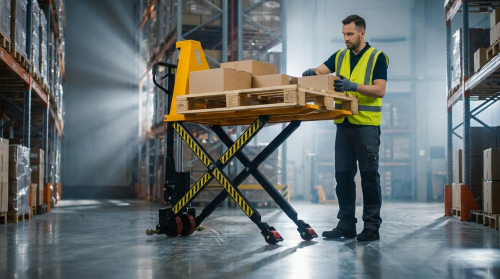
Pallet jacks operated as high-utilization assets in warehouses, distribution centers, and manufacturing plants. Their hydraulic lifting systems required correct diagnosis and maintenance to avoid unsafe failures and unplanned downtime. This guide explained how manual pallet jack hydraulics worked, how to diagnose lift problems step by step, and how to perform repairs, rebuilds, and predictive maintenance. It concluded with a concise summary of practices that improved lifting reliability and operator safety.
Across the article, the focus stayed on hydraulic components, handle linkages, valves, and typical failure modes that caused poor lifting or uncontrolled lowering. The diagnostic sections covered bleeding air, checking oil levels and contamination, and separating handle issues from pump and valve faults. The repair sections addressed valve and linkage adjustments, seal and wheel replacement, and structured hydraulic unit rebuild and testing. The final section connected these tasks to modern inspection regimes, digital tools, and long-term reliability strategies for pallet jack fleets.
How Pallet Jack Lifting Systems Work
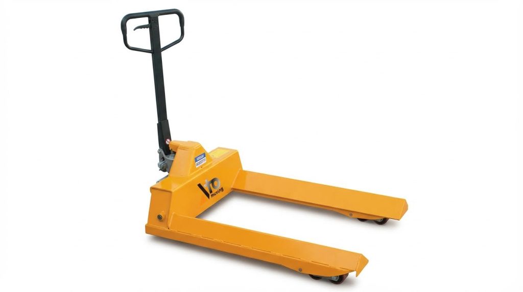
Manual pallet jack lifting systems converted low operator input into relatively high lifting force through a compact hydraulic circuit. The system integrated a pump, reservoir, cylinder, and valves with a mechanical linkage in the handle. Understanding this interaction allowed technicians to diagnose lift problems quickly and select appropriate repair strategies. The following subsections described the main hydraulic elements, the kinematic chain from handle to forks, and typical failure patterns observed in service.
Key Components Of Manual Pallet Jack Hydraulics
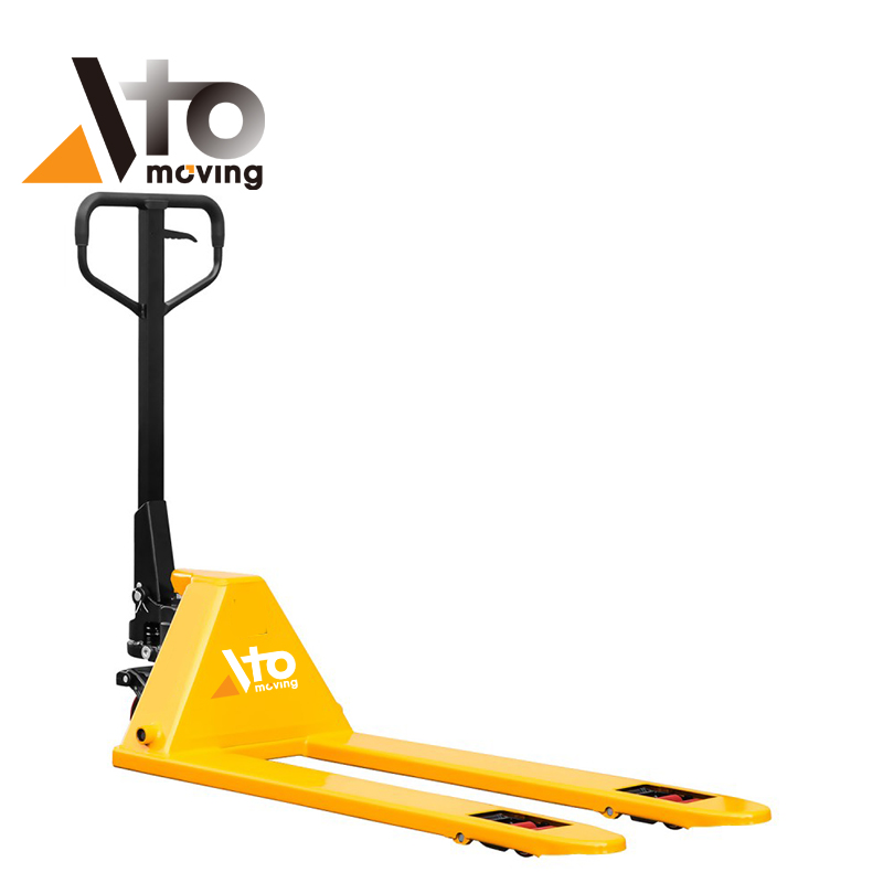
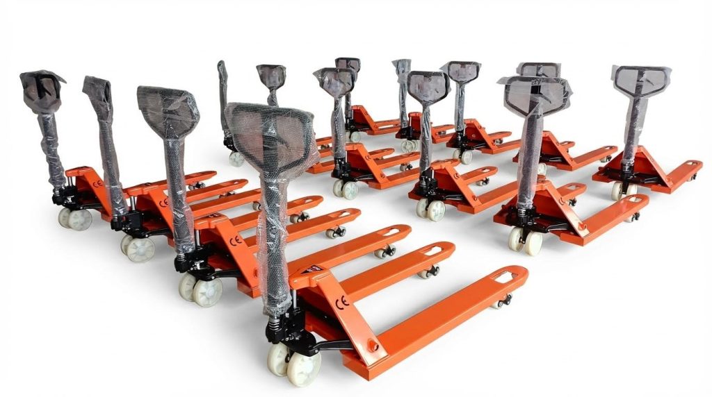
A manual pallet jack used a single-acting hydraulic cylinder that raised the fork frame when pressurized. A small hand pump, driven by the handle motion, pressurized hydraulic oil drawn from an integrated reservoir. Check valves controlled suction from the reservoir and discharge into the cylinder, ensuring one-way flow during each pump stroke. A lowering valve provided a controlled return path for the oil back to the reservoir when the operator selected the release position. Typical systems operated with mineral-based hydraulic oil compatible with ISO viscosity grades similar to ISO VG 32 or 46. The pump body, reservoir, and valve bores formed a single compact hydraulic unit mounted between the fork arms. Seals and O-rings at the piston rod, pump plunger, and valve plugs maintained system tightness and prevented air ingress. Correct oil level and cleanliness were critical, because even small air volumes or particles affected lift height and stability.
Handle Linkage, Valves, And Lift Kinematics
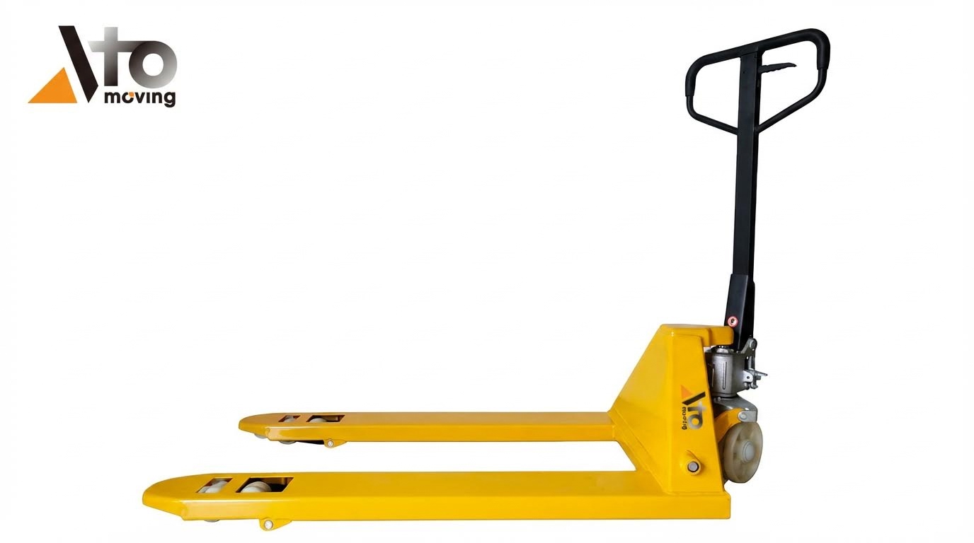
The operating handle performed three functions: steering, pumping, and valve actuation. A mechanical linkage inside the handle head transferred small angular movements into linear motion at the pump plunger and valve stems. In the “lift” position, the linkage engaged the pump plunger while keeping the lowering valve closed, so each handle stroke increased cylinder pressure. In the “neutral” position, the linkage isolated both pump and lowering valve, allowing the jack to roll without changing fork height. In the “lower” position, the linkage opened the lowering valve, connecting the cylinder to the reservoir and letting the forks descend under load. The kinematics relied on correctly adjusted pins, clevis joints, and return springs to ensure full valve travel without over-stressing components. Wear or bending in these joints changed valve timing, which directly affected lifting, holding, and lowering performance.
Common Failure Modes In Lift Mechanisms
Typical lift failures included no lift, partial lift, or forks slowly sinking under load. Air in the hydraulic circuit, often introduced by low oil level or tilted operation, caused spongy lifting and reduced maximum height until the system was bled. Contaminated or degraded oil led to sticking check valves, internal leakage, and accelerated wear of pump and cylinder surfaces. Worn seals at the cylinder or pump plunger allowed internal bypass, so the handle moved but pressure did not build sufficiently. Misadjusted or damaged lowering valves caused continuous internal leakage, resulting in forks that would not stay raised or that refused to lift at all. Mechanical issues in the handle linkage, such as elongated holes, bent rods, or broken springs, prevented valves from fully opening or closing at the correct positions. Overloading beyond rated capacity accelerated all these failure modes and increased the risk of sudden loss of lift or uncontrolled lowering, which affected safety compliance with FEM and similar standards.
Step-By-Step Diagnosis Of Lift Problems
Systematic diagnosis of pallet jack lift issues reduced downtime and avoided unsafe improvisation. Technicians typically moved from basic safety checks to targeted hydraulic tests. This staged approach separated simple field fixes from faults requiring workshop-level repair.
Safety Lockout, Support, And Inspection Basics
Technicians first secured the pallet jack on a level, clean surface without a load. They chocked wheels where roll-away was possible and lowered forks fully to remove stored energy. For electric units, they disconnected the battery and followed lockout/tagout procedures to prevent unintended operation. Visual inspection then focused on cracked welds, bent forks, damaged handle linkages, and leaking hydraulic components. They checked wheels and rollers for flat spots or misalignment that could mask as lift problems. Only after confirming structural integrity and basic safety did they proceed to hydraulic troubleshooting.
Bleeding Air From The Hydraulic Circuit
Air ingress frequently caused poor or intermittent lifting in manual pallet jacks. The standard bleed procedure used the control lever in the lowering or release position while the technician pumped the handle approximately ten times. This cycling purged trapped air from the pump and cylinder back to the reservoir. The jack was then tested by returning the lever to the lift position and pumping under no load. If lift height and stroke normalized, no further hydraulic disassembly was necessary. Persistent spongy response or partial lift after several bleed cycles indicated additional faults such as low oil level or internal leakage.
Checking Oil Level, Contamination, And Leaks
If bleeding did not restore lift, technicians checked hydraulic oil level and condition. They carefully removed the fill plug with forks fully lowered to minimize pressure in the reservoir. For most pallet jacks, correct level sat roughly 25 mm below the top of the reservoir or at the lower edge of the fill port. Dark, milky, or particle-laden oil indicated water ingress or wear debris, which reduced volumetric efficiency and accelerated seal damage. External inspection around the pump body, cylinder, hose connections, and shaft seals helped locate active leaks. Where contamination was evident, a full drain, flush, oil replacement, and subsequent bleeding formed part of the diagnostic and corrective process.
Isolating Handle, Linkage, And Pump Valve Faults
When correct oil level and successful bleeding still failed to restore lift, technicians isolated mechanical from hydraulic faults. They disconnected the lifting linkage from the handle lever and manually actuated the pump input to see whether the jack raised. If the unit lifted with the linkage disconnected, the fault lay in the handle, pivot bushings, or linkage geometry, often correctable through adjustment or part replacement. If lift remained absent, the problem shifted to the pump block, commonly the check or lowering valve not sealing. Technicians then inspected valve springs, seats, and spools for scoring or debris and replaced defective valves or seal kits. Persistent internal bypass or unstable pressure after these steps typically triggered a full hydraulic unit rebuild or replacement based on cost and condition.
Repair, Rebuild, And Predictive Maintenance
Repairing pallet jack lifting systems required a structured approach that separated simple adjustments from full hydraulic rebuilds. Technicians minimized downtime by starting with external, in‑situ corrections before removing the pump unit. Predictive maintenance practices, supported by digital tools and inspection data, extended component life and reduced unexpected failures. This section detailed practical field adjustments, component replacement, controlled test procedures, and modern condition‑based maintenance methods.
Adjusting Valves, Handles, And Linkages
Technicians first verified that the control handle moved freely through raise, neutral, and lower positions without sticking. Incorrectly adjusted lowering or bypass valves often caused symptoms such as no lift, creeping lowering, or delayed response. A typical procedure placed the control lever in the neutral or mid position, loosened the valve locknut, and then turned the adjustment screw in small increments while cycling the jack under no load. After each change, they checked that the jack raised, held, and lowered smoothly, confirming that the valve fully seated in the hold position and opened adequately in the lower position. If lifting returned when the linkage was disconnected, the fault usually lay in the handle cam, pins, or connecting rods, which required re‑bushing, re‑pinning, or replacement to restore correct kinematics.
Replacing Seals, Pumps, And Wheel Assemblies
Persistent external leakage at the lift cylinder, pump body, or handle base indicated worn seals or O‑rings. Technicians depressurized the system, fully lowered the forks, and drained hydraulic oil into a clean container before disassembly. Seal kits typically included rod seals, wipers, static O‑rings, and backup rings that had to match the jack’s model and hydraulic fluid compatibility. When internal leakage caused low or no lift despite correct oil level and bleeding, replacing the entire pump cartridge or valve block was often more economical than machining worn parts, especially when repair cost approached 60% of a new unit. Wheel and roller replacement restored tracking and reduced shock loading on the hydraulic unit; mechanics supported the frame, removed cotter pins or retaining rings, pressed out worn wheels, greased new bearings, and verified free rotation and straight‑line travel under load.
Rebuilding Hydraulic Units And Test Procedures
A full hydraulic unit rebuild started only after confirming that simple bleeding, oil changes, and valve adjustments did not restore lifting performance. The technician removed the pump module from the chassis, cleaned the exterior, and disassembled it on a clean bench following the service manual sequence. Components such as gears, plungers, check valves, and valve seats were inspected for scoring, pitting, cracks, and excessive clearances against manufacturer limits. After installing new seals and any worn hard parts, the unit was reassembled using specified torque values and compatible sealants. Bench testing involved filling with clean ISO‑grade oil, manually priming, and cycling the pump at low speed while monitoring pressure buildup, leak‑tightness, and the jack’s ability to raise and hold a rated test load without drift over a defined time interval.
Digital Tools And Predictive Maintenance Practices
Digital maintenance systems supported more reliable pallet jack operation by tracking usage hours, service history, and inspection findings. Fleet managers logged weekly checks of oil level, visible leaks, wheel wear, and lifting behavior into computerized maintenance management systems. Simple sensors or manual readings of hydraulic oil temperature, contamination indicators, and pressure test results helped identify degrading pumps before complete failure. Data trends triggered condition‑based tasks such as oil changes every 2 000–3 000 operating hours, pre‑emptive seal replacement, or scheduled wheel kit changes in high‑throughput areas. Integration with safety inspection regimes, including annual FEM 4.004 checks where applicable, ensured that lift performance, structural integrity, and braking remained within regulatory and manufacturer limits while minimizing unplanned downtime.
Summary: Reliable And Safe Pallet Jack Lifting
Pallet jack lift reliability depended on understanding the hydraulic circuit, mechanical linkage, and wheel assemblies as one system. Typical lifting faults traced back to air in the oil, low or contaminated hydraulic fluid, misadjusted lowering valves, or worn seals and valves inside the pump. Systematic diagnosis started with lockout, visual inspection, and bleeding the hydraulic unit, then progressed to oil level checks, leak tracing, and isolation of handle versus pump faults by disconnecting the linkage. When the jack still failed to lift after bleeding and topping oil, technicians usually found internal valve leakage, damaged seals, or scored components that required repair or replacement.
Industry practice moved toward structured maintenance programs and FEM 4.004–compliant inspections at least annually, supported by weekly functional checks. Predictive maintenance used digital work orders, condition logs, and, for larger fleets, sensor-based monitoring of usage hours and fault history to schedule oil changes and rebuilds before failure. In repair decisions, shops compared rebuild cost and remaining service life against the price of a new pump or jack, often replacing units when housing damage or out-of-tolerance wear exceeded economic repair limits. Implementation in the field required standard procedures for bleeding, valve adjustment, oil service, and wheel replacement, supported by correct tools, OEM-equivalent parts, and trained personnel.
Going forward, higher utilization in logistics and tighter safety expectations pushed toward more frequent inspections, better contamination control, and clearer documentation. Electric pallet trucks added battery and control diagnostics but still relied on sound hydraulic and mechanical fundamentals. A balanced approach combined conservative safety margins, adherence to load ratings, and regular preventive tasks with selective upgrades such as improved seal kits and cleaner hydraulic oils. Organizations that embedded these practices into their maintenance culture achieved longer jack life, fewer unplanned stoppages, and safer handling operations.