Hydraulic lift platforms answer a core question in projects that search for what is hydraulic lift platform and how it really works in the field. This article explains how hydraulic circuits, cylinders, and platform structures create controlled vertical motion for goods and personnel.
You will see how these platforms support truck loading, warehouse handling, construction work, and integration with conveyors, AGVs, and cobots. The article also links these applications to safety devices, international standards, and inspection rules that govern hydraulic lift design.
From there, the focus moves to mechanical and hydraulic fail‑safe features, overload protection, and control logic that prevent accidents. The final section compares key design choices, risks, and lifecycle benefits so engineers, EHS staff, and fleet managers can specify and operate hydraulic lift platforms with clear, defensible criteria.
Core Mechanics Of Hydraulic Lift Platforms
Engineers who ask what is hydraulic lift platform focus first on the core mechanics. These platforms convert hydraulic pressure into controlled vertical motion with repeatable accuracy. This section explains how circuits, structures, and controls work together, and how energy limits shape duty cycles. It builds the base for later sections on applications and safety design.
Hydraulic Circuits, Cylinders, And Power Units
A hydraulic lift platform uses a closed fluid circuit to raise and lower loads. The power unit includes an electric motor, hydraulic pump, reservoir, filter, and safety valves. The pump creates flow, and pressure builds only when the load resists movement. Cylinders convert this pressure into linear force on the scissor, mast, or linkage.
Key design choices include:
- Working pressure range, often in the 10–25 megapascals band.
- Cylinder bore and stroke sized for rated load and lift height.
- Reservoir volume large enough to limit oil temperature rise.
Engineers select gear, vane, or piston pumps based on required flow, noise limits, and duty class. Relief valves protect the system from overpressure, while check valves prevent unintended descent if supply pressure drops. For vehicle-mounted platforms, compact DC power packs often run from the vehicle battery and alternator.
Platform Structures, Linkages, And Guidance
The platform structure carries both static and dynamic loads. Designers usually use welded steel or aluminum sections with stiffeners under the deck. The structure must resist bending, torsion, and local wheel loads from pallet trucks or carts.
Common lifting geometries include:
| Type | Main feature | Typical use |
|---|---|---|
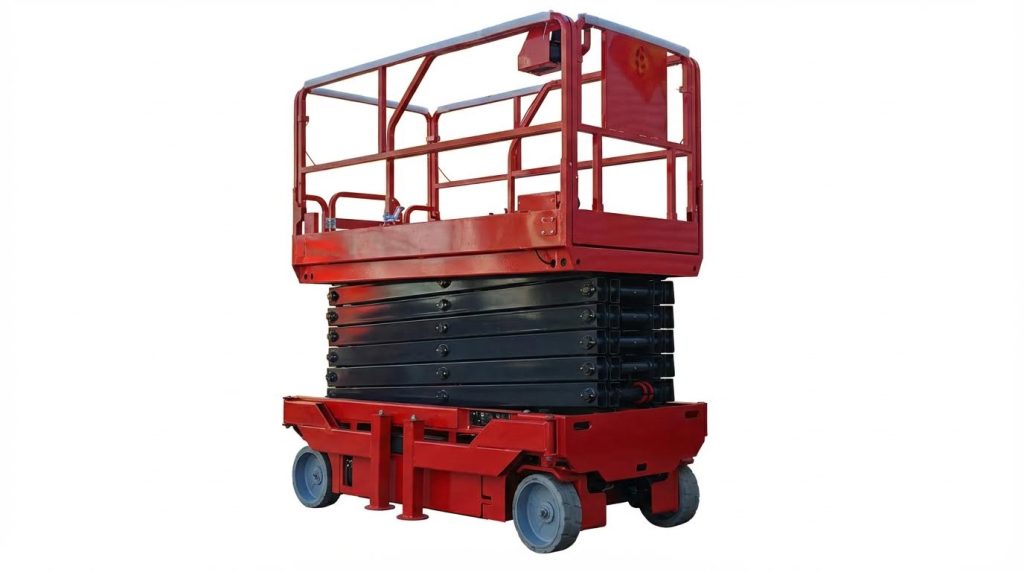
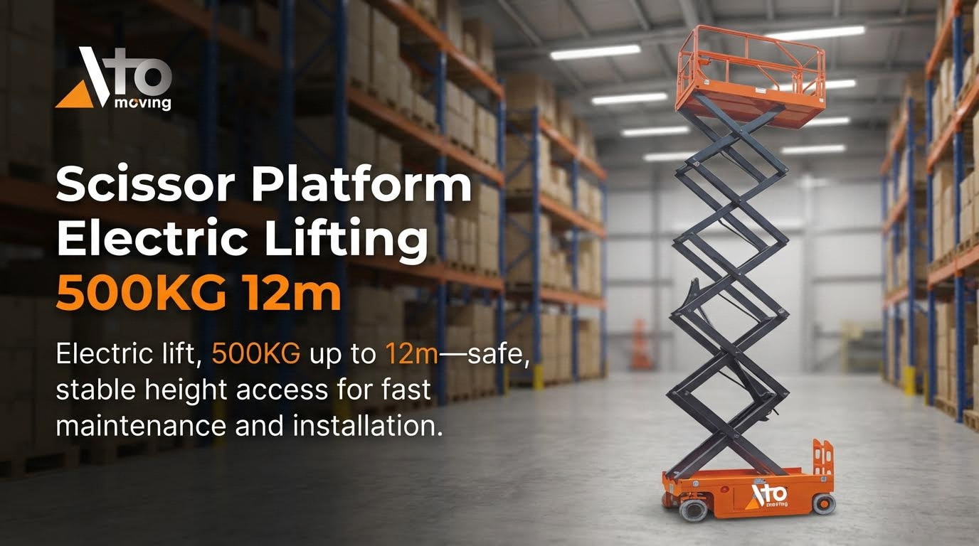
| Scissor lift | Crossed arms with central or end cylinder | Dock and factory lift tables |
| Vertical mast | Telescopic or rail-guided carriage | Goods lifts and work platforms |
| Parallel arm / tail lift | Arms pivot from vehicle frame | Truck rear lifts |
Guidance systems keep the platform stable and aligned. These may use slide rails, rollers in C-channels, or precision mast profiles. Proper guidance reduces side load on cylinders and pins, lowers wear, and improves ride quality for personnel platforms. Engineers check deflection limits so the deck stays level under rated load.
Control Logic, Valving, And Motion Profiles
Control logic answers how the platform starts, moves, and stops. Basic systems use direct push-button controls with contactors and a simple up/down valve block. Advanced systems use relay logic or programmable controllers to manage speed ramps, sequencing, and interlocks.
Valves shape the motion profile:
- Directional valves route flow for raising or lowering.
- Flow control valves set lifting and lowering speeds.
- Counterbalance or load-holding valves prevent runaway descent.
Engineers tune valve sizes to balance cycle time and smoothness. Too high a flow can cause jerk and shock loads. Soft-start and soft-stop profiles reduce stress on welds, pins, and cylinder seals. Control stations usually include emergency stop and deadman functions so motion only occurs while the operator commands it.
Energy Use, Duty Cycles, And Thermal Limits
Energy use in a hydraulic lift platform depends on load, lift height, cycle frequency, and system efficiency. Typical hydraulic efficiencies fall in the 80–90 percent range for well-designed systems. Losses appear as heat in the oil, especially during throttled lowering or pressure holding.
Duty cycle describes how long the unit runs within a time window. Designers classify platforms for light, standard, or heavy duty based on expected cycles per hour and total daily run time. High duty applications need larger reservoirs, oil coolers, and higher efficiency pumps. Thermal limits protect seals and hoses from oil temperatures that exceed recommended values.
Engineers often compare alternatives using:
- Energy per cycle (kilojoules or kilowatt-hours per lift).
- Peak motor power versus available electrical supply.
- Allowable oil temperature rise over the longest shift.
Correct sizing avoids motor overload trips and premature oil degradation. It also supports stable performance when platforms run in hot climates or enclosed vehicle bodies.
Industrial And Vehicle-Mounted Applications
Industrial and vehicle-mounted uses answer a core search question: what is hydraulic lift platform capability in real work. This section explains how platforms support trucks, warehouses, construction, waste, and automation links. It compares duty patterns, load ranges, and environment demands. It also highlights how design choices shift when platforms work with conveyors, AGVs, and cobots.
Truck Tail Lifts And Mobile Service Vehicles
Vehicle-mounted hydraulic lift platforms on trucks and vans handle ground-to-bed transfer. Typical units lift 500 kilograms to over 3 000 kilograms and match vehicle floor heights up to about 1 600 millimetres. Rail-guided or parallel arm designs suit light vans, while heavy fold-away or slider lifts suit freight trucks. Platform materials are usually aluminium for weight saving or steel for impact resistance.
In logistics fleets, operators use tail lifts for palletised goods, roll cages, and bulky parcels. Mobile service vehicles use smaller platforms to load compressors, generators, and tool cabinets. Common control layouts include fixed external pendants plus optional radio remotes for better visibility. Designers must size power packs to support repeated lift cycles at delivery stops without overheating vehicle electrical systems.
Key engineering concerns include:
- Stable support on uneven roads and kerbs
- Anti-slip decks and edge restraints for trolleys
- Automatic mechanical locks when stowed for travel
- Protection of cylinders and hoses from road spray and debris
Warehouse, Manufacturing, And Assembly Uses
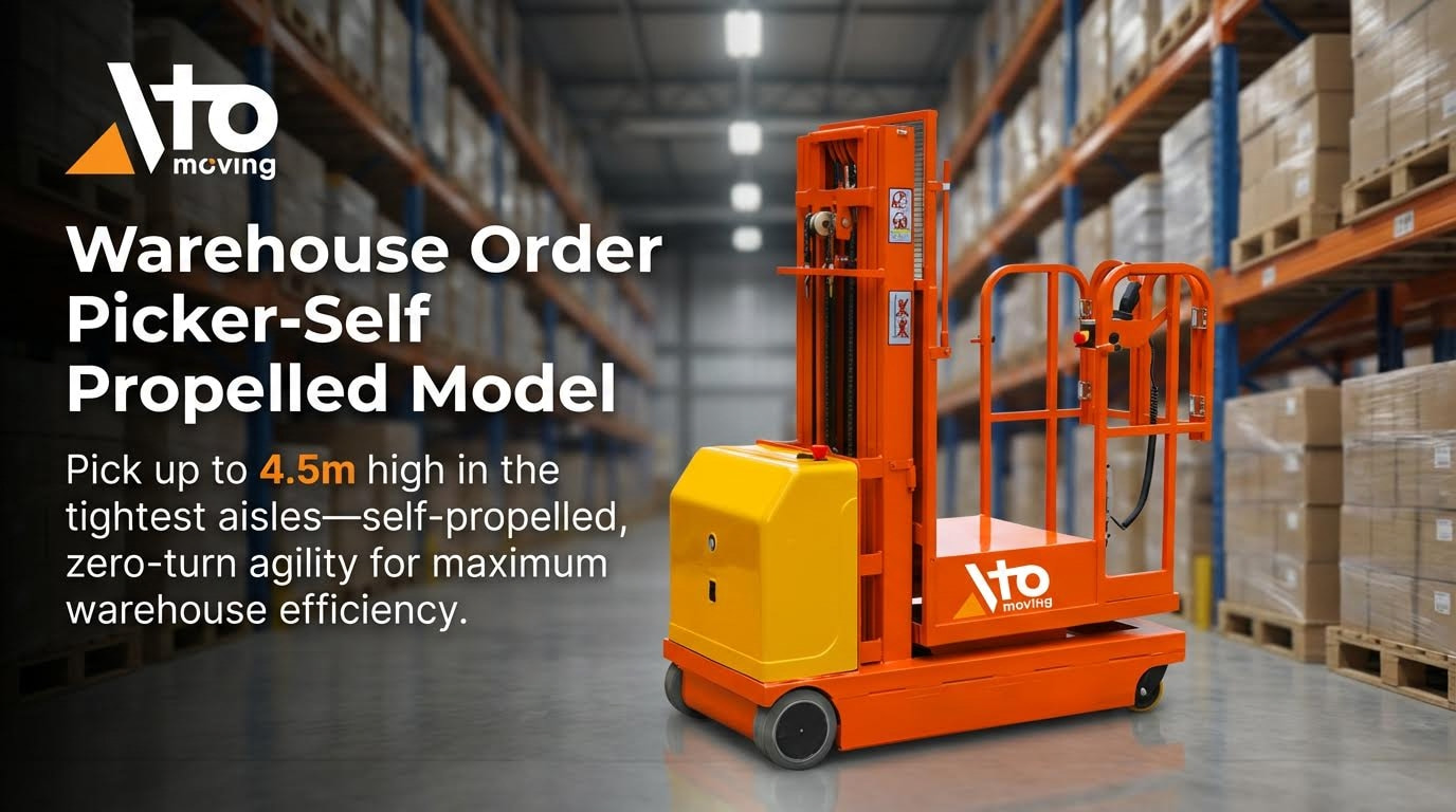
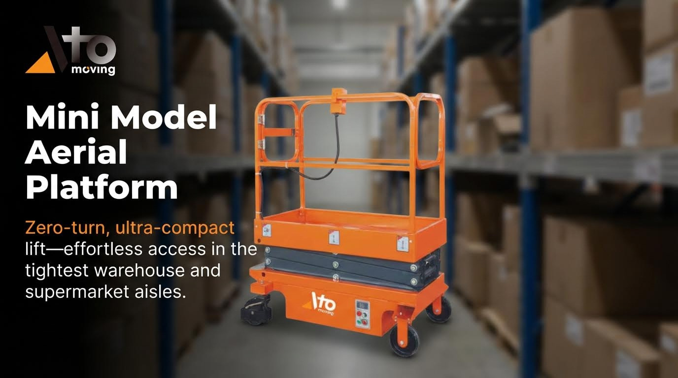
In warehouses, hydraulic lift platforms work as dock lifts, scissor tables, and order-picking platforms. They bridge the height gap between truck beds, docks, and floor levels to reduce manual lifting. Typical deck sizes range from about 800 × 1 600 millimetres for workstations to over 2 500 × 2 000 millimetres for pallet handling. Lifting speeds usually fall within 4–10 metres per minute, balanced against stability and load shift risk.
Manufacturing and assembly lines use lift tables to set ergonomic working height. Operators raise or lower heavy parts, fixtures, or jigs instead of bending or reaching. This reduces musculoskeletal strain and supports consistent assembly quality. Conveyor-top lift tables move products between process levels and allow fine height trim for line balancing.
| Application | Main Function |
|---|---|
| Dock lift | Align floor and truck bed for pallet trucks |
| Assembly lift table | Set part height for ergonomic work |
| Order picker platform | Raise personnel to rack levels |
| Conveyor lift table | Change elevation in automated lines |
Designers must consider duty cycles, oil temperature rise, and maintenance access. High-throughput sites benefit from easy-to-clean layouts and quick-change hose and seal designs.
Construction, Waste, And Outdoor Operations
Construction and waste tasks push hydraulic lift platforms into harsh outdoor duty. Platforms handle bricks, blocks, rebar bundles, bins, and demolition debris. Loads are often irregular and off-centre, so wide decks and high stiffness help keep tilt within safe limits. Outdoor lifts also face wind loads, rain, dust, and temperature swings.
Common outdoor formats include:
- Vehicle-mounted bin lifts on refuse trucks
- Scissor lifts for façade work and fit-out
- Goods lifts between ground and upper slabs
Waste handling lifts need robust hinge pins, impact-resistant stops, and strong backplates. They work with frequent short cycles during collection rounds. Construction platforms often integrate with scaffolds or building structures and must resist corrosion from cement dust and moisture. Designers select coatings, hose sheathing, and seal materials that tolerate UV, grit, and chemicals.
Safety engineering focuses on overload protection, guarded pinch points, and secure attachment to host structures or vehicles. Controls must stay usable with gloves and in low visibility. Emergency lowering systems are critical when power fails at height.
Integration With Conveyors, AGVs, And Cobots
Modern facilities link hydraulic lift platforms with conveyors, automated guided vehicles (AGVs), and collaborative robots. Here the answer to what is hydraulic lift platform extends beyond lifting. The platform becomes a controlled node in a material flow system. Height, timing, and position must align with upstream and downstream equipment.
Typical integration patterns include:
- Conveyor-top scissor lifts between mezzanine and ground
- Lift stations where AGVs deposit or collect pallets
- Robot-tended lift tables that present parts at fixed positions
Control logic often uses limit switches, encoders, or position sensors. These signals feed PLCs or warehouse control systems. The system then coordinates lift motion with conveyor starts and AGV routing. Designers must define clear safety zones with light curtains, interlocked gates, or pressure mats.
Compared with stand-alone platforms, integrated units need tighter repeatability in stopping height and smoother motion profiles. They also need predictable cycle times to keep line takt time. Hydraulic power units may run more often, so engineers size reservoirs and coolers to keep oil within safe temperature limits during continuous shifts.
Safety Features, Standards, And Compliance
Safety design decides whether a hydraulic lift platform stays reliable over its full life. Engineers must link mechanical design, hydraulic controls, and operator behavior to one clear safety concept. Global users search what is hydraulic lift platform to understand both function and risk. This section explains how fail-safes, guarding, control logic, and codes work together to keep loads and people safe.
Mechanical And Hydraulic Fail-Safe Devices
Fail-safe devices must keep the platform from dropping or moving uncontrolled after a fault. Designers protect the load path from cylinder, hose, or valve failure using multiple layers of defense. Typical hydraulic lift platforms use:
- Pressure relief valves to cap system pressure and protect cylinders and hoses.
- Pipe‑rupture or hose‑burst valves at cylinders to stop rapid descent if a line fails.
- Check valves and pilot‑operated check valves to lock the platform when controls are neutral.
- Mechanical locks, chocks, or maintenance props for work under a raised platform.
OSHA and ANSI aerial lift rules required critical hydraulic parts to meet defined bursting safety factors. Critical parts include those whose failure would cause free fall or free rotation. Non‑critical parts could use lower factors but still needed a minimum 2:1 margin. For vehicle‑mounted work platforms, standards also limited maximum down speed after failure, so the platform could not drop faster than a defined rate. Engineers should verify that all fail-safe devices default to the safe state on power loss.
Guardrails, Anti-Slip Design, And Fall Protection
Any hydraulic lift platform that carries people must act as a safe work surface. Structural guardrails form the first barrier. Typical practice uses a top rail, mid rail, and toe board with defined minimum heights and strength. Rails must resist expected side loads without permanent bend.
The floor must reduce slip risk in wet or oily conditions. Designers often use:
- Textured steel plate or punched grating.
- High‑friction coatings rated for industrial traffic.
- Positive drainage paths so water does not pool.
Regulations required workers on aerial platforms to stand on the basket floor, not on ladders or boxes. Personal fall arrest or travel restraint systems had to anchor to approved points on the boom or basket. For building maintenance platforms, codes required full perimeter guardrails and often mid‑rails and toe boards. Engineers must also shield workers from moving chains, rollers, and lift mechanisms with fixed guards or screens when contact is possible.
Overload Limits, Interlocks, And Control Safety
Overload control is central to safe hydraulic lift platform operation. Designers size cylinders, pins, and platforms for a rated load plus a safety factor. They then add devices that stop motion before structural limits are reached. Common elements include:
- Overload sensors or pressure switches that block lift when load exceeds rating.
- Current or power monitoring on electric power units to detect abnormal demand.
- Limit switches to prevent travel beyond safe top and bottom positions.
Interlocks link doors, gates, and stabilizers to platform motion. For example, platform travel may be blocked if a gate is open or stabilizer legs are not deployed. OSHA rules forbade traveling vehicles with work platforms raised above a small height except at inching speed. Control stations require clearly marked up, down, and emergency stop functions. Emergency stop buttons must latch, be red, and cut power while applying brakes. Controls should be hold‑to‑run so the platform stops when the operator releases the button or joystick.
Inspection, Maintenance, And Regulatory Codes
Codes and standards gave a structured framework for design and upkeep. In the United States, ANSI A92.2 defined design and construction rules for vehicle‑mounted elevating and rotating work platforms. OSHA rules referenced these standards and added detailed inspection and training duties. Building maintenance platforms used other OSHA subparts that covered suspension ropes, design factors, and weather loads.
Regulations required daily function checks of lift controls before use. A competent person had to inspect aerial lifts and manlifts on regular cycles, often monthly or every 30 days. Limit switches needed weekly verification. Suspension ropes on powered platforms required monthly detailed checks, with written records. Replacement criteria included broken wires, corrosion, kinks, or heat damage.
Electrical systems had to follow workplace wiring rules, with dedicated circuits and lockable disconnects. Owners of building‑mounted platforms had to provide written proof that tests confirmed load capacity, stability, and anchorage strength. Training programs had to teach hazard recognition, emergency procedures, and correct use of personal fall protection. For operators asking what is hydraulic lift platform in a compliance context, these codes define how the machine must be designed, tested, and used to stay legal and safe.
Summary Of Design Choices, Risks, And Benefits
Engineers asking what is hydraulic lift platform need a clear view of trade-offs. Design choices link directly to load range, duty cycle, and working environment. Each choice shifts risk between structural failure, hydraulic faults, and control errors. A structured summary helps align engineering, safety, and operations teams.
Key design choices cluster around four areas. First is architecture: scissor, mast, tail lift, or dock lift. This affects guidance stability, platform deflection, and integration with vehicles or buildings. Second is hydraulic design: single vs multiple cylinders, working pressure range, valve strategy, and energy management. Third is control concept: wired or wireless controls, interlocks, and emergency functions. Fourth is safety envelope: guardrails, anti-slip surfaces, overload protection, and compliance with standards such as ANSI A92 and OSHA rules.
Main risks fall into mechanical, hydraulic, electrical, and human factors. Typical failure modes include hose rupture, uncontrolled descent, overload, crush points, and fall hazards. Modern platforms reduce these risks with rupture valves, pressure relief valves, mechanical locks, and speed limits for both lifting and lowering. Guardrails, toe boards, and non-slip decks address fall and slip hazards, while interlocks prevent operation with open gates or during overload.
The benefits remain strong across logistics, manufacturing, construction, and building maintenance. Platforms cut manual handling, lower injury rates, and shorten loading or access times. They also enable use of vertical space, which improves site,
Frequently Asked Questions
What is a hydraulic lift platform?
A hydraulic lift platform is a device that uses liquid pressure to elevate heavy objects. It operates by introducing incompressible oil into a cylinder, which pushes a piston upward. This mechanism allows for smooth and controlled lifting of loads. Hydraulic Lift Guide.
Why are hydraulic lift platforms useful?
Hydraulic lift platforms are useful because they allow you to move heavy objects with much less effort. They provide precise control and are capable of lifting heavier loads compared to other systems. These lifts are commonly used in warehouses, construction sites, and manufacturing facilities. Lifting Mechanics.
What are the hazards of using hydraulic lift platforms?
Using hydraulic lift platforms can pose several hazards if not properly maintained or operated. High pressures can cause ruptures, while low pressures may lead to the ram unexpectedly dropping, potentially injuring people or damaging items below. Always inspect and service the equipment regularly according to the manufacturer’s instructions. Hydraulic Safety Tips.
What are some common types of hydraulic lift platforms?
Common types of hydraulic lift platforms include scissor lifts, boom lifts, and manlifts. Each type serves different purposes and applications depending on the specific needs of the task at hand. For example, scissor lifts are ideal for vertical elevation, while boom lifts offer extended reach. Types of Hydraulic Lifts.