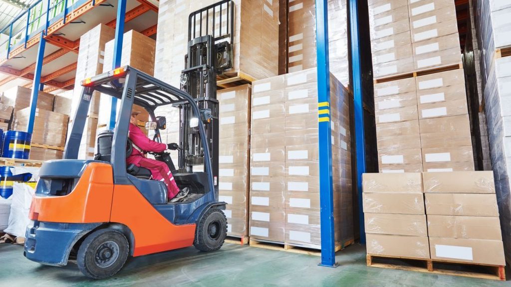
Scissor lift stability is not guesswork; it is the result of chassis design, scissor geometry, hydraulics, and strict load control. This guide explains how stable are scissor platform lifts in real-world use by linking structural design, standards, and operator behavior. You will see how capacity, foundations, wind, and movement interact, and what inspections and practices keep platforms upright and predictable. Use it as a practical engineering and safety reference when selecting, installing, and operating any scissor platform lift or aerial platform. Ensure proper handling with equipment like manual pallet jack.
How Scissor Lifts Achieve Structural Stability
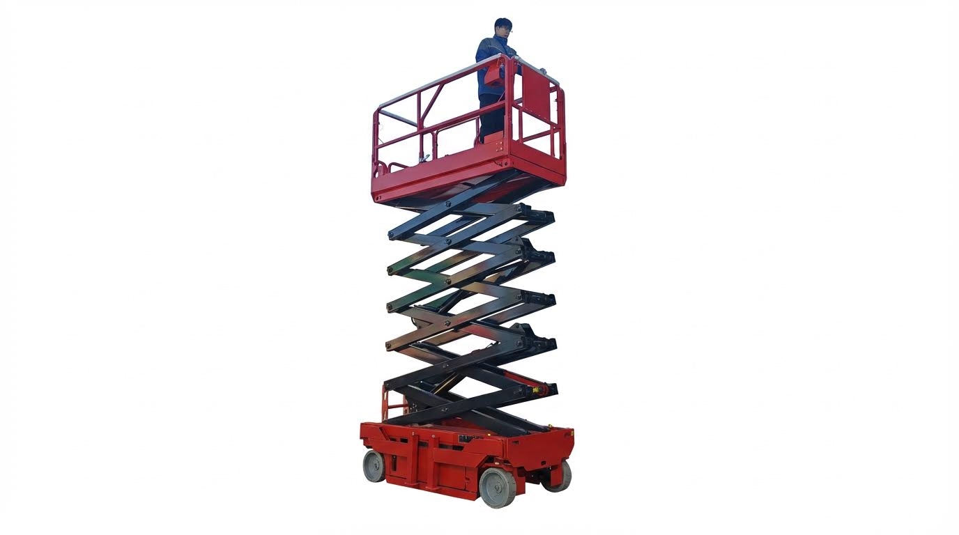
Chassis, scissor geometry, and center of gravity
To understand how stable are scissor platform, start with the base mechanics. Stability comes from a wide, stiff chassis, correctly proportioned scissor arms, and a controlled center of gravity (CG) that stays inside the support polygon throughout the lift stroke.
- Chassis role in stability
- Distributes weight uniformly into the ground to prevent vibration, rolling, or tilting during lifting (base chassis for weight distribution).
- Wheelbase length and track width define the “stability triangle” or polygon.
- High-strength steel sections and cross‑bracing increase torsional stiffness, limiting twist under offset loads.
- Scissor geometry
- Pairs of crossing arms form a pantograph; as angle closes, vertical lift increases and horizontal span reduces.
- Arm length, pin spacing, and cross‑section are sized to carry rated loads without excessive deflection.
- Symmetrical arm layout keeps load paths balanced left‑to‑right, reducing side‑tilt risk.
- Center of gravity control
- Platform and load CG must remain inside the footprint defined by wheels/outriggers for all allowed heights.
- Heavier structural elements are kept low in the chassis to lower overall CG.
- Uneven or deformable surfaces increase effective CG excursion and raise tip‑over risk (surface and movement recommendations).
Engineering note: geometry, flexibility, and tip‑over threshold
Research showed fundamental natural frequencies of scissor platform lift typically in the 0.30–2.08 Hz range, indicating that structural flexibility and dynamic excitation can interact with stability limits. Increasing structural flexibility generally lowers the tip‑over threshold, and the risk of overturning also depends on ground slope and the rate of tilt input. Workers should avoid vigorous horizontal movement on the platform, especially when fully elevated, and the lift should not be used on highly deformable or uneven supports such as timber planks or soft soil surfaces. (flexibility and tip‑over risk)
From an engineering perspective, the question “how stable are aerial platform” is answered by how well these three elements are matched. A stiff, wide chassis with optimized scissor geometry and a low, well‑managed CG gives a large stability margin even near full height, provided the unit is used on suitable ground and within its rated envelope.
Hydraulics, locking devices, and structural stiffness
Hydraulics and mechanical locks do not just lift the platform; they also control motion and hold the structure in a stable, predictable configuration. Structural stiffness then limits deflection so the platform stays level under rated load.
| Element | Main stability function | Key engineering considerations |
|---|---|---|
| Hydraulic cylinders | Provide smooth lifting force and allow fine balance adjustments, reducing shock and oscillation during elevation | Must resist leakage and sudden pressure loss; compliant with hydraulic design standards such as GB/T 3766 and component standard GB/T 7935 (hydraulic system compliance) |
| Hydraulic control & speed limits | Limit vertical and travel speeds to keep dynamic loads within the stability envelope | Typical requirements: rise/fall speed ≤ 0.4 m/s, travel speed when raised ≤ 0.4 m/s, and when closed ≤ 0.7 m/s (performance requirements) |
| Mechanical locking devices | Physically block unintended descent and add redundancy if hydraulic pressure is lost | Must engage positively and be verified in pre‑use inspections to ensure they hold the platform at set heights (lock function checks) |
| Platform and arm stiffness | Limit bending and sway so the platform remains level and predictable under load | Deflection of mobile scissor lifts should not exceed about 0.5% of maximum height, and platforms should withstand 1.33× rated capacity for repeated cycles without permanent deformation (deflection and overload test) |
| Guardrails and structural safety features | Prevent falls and provide lateral stiffness to the platform assembly | Guardrail height typically at least 1.1 m, with bar spacing under 0.55 m to meet stability and fall‑protection criteria (guardrail requirements) |
- Hydraulic system condition and stability
- Leaks, spongy response, or unusual noises indicate internal bypassing or air, which can increase bounce and reduce positional control (inspection for leaks and abnormal movement).
- Regular lubrication and cable or linkage tension checks help maintain consistent weight distribution and prevent uneven lifting that could tilt the platform (lubrication and tension checks).
- Locking devices and redundancy
- Mechanical locks or safety props are designed to carry load independently of hydraulic pressure during maintenance or extended parking.
- Inspection routines should verify full engagement of locks before personnel work under or around raised structures.
- Structural stiffness and perceived stability
- Higher stiffness reduces sway, which directly improves the operator’s perception of how stable are order picking machines at height.
- Designers balance weight and stiffness; excessive flexibility increases dynamic amplification and tip‑over potential under lateral disturbance.
In combination, controlled hydraulic motion, positive locking, and adequate stiffness ensure that the platform does not just reach the working height, but stays there with minimal deflection and movement. When these systems are correctly designed, maintained, and used within specified limits, warehouse order picker provide a high level of structural stability for both people and loads.
Load Distribution, Standards, And Performance Limits
How stable are scissor lifts depends heavily on how the load is distributed, which standards the machine meets, and whether it is operated within tested performance limits. This section breaks that into three practical questions: how much you can load, what the ground and foundation must provide, and how motion, wind, and operators affect real stability.
Rated capacity, load placement, and deflection
Rated capacity is not a “nice-to-have” number; it is the boundary of the tested stability envelope. Modern mobile and automotive scissor lifts are typically designed and tested to carry loads from about 6,000–12,000 lb, depending on model and rise height. Mid‑rise units commonly support 6,000–9,000 lb, while full‑rise units handle roughly 9,000–12,000 lb. Staying inside that envelope is the first control on how stable are scissor platform lift in real use.
Beyond total weight, where you put the load controls platform deflection and center-of-gravity (COG) shift. Standards for mobile scissor lifts typically limit elastic deflection to a small fraction of platform span or lift height to ensure the structure behaves like a stiff frame, not a springboard. For example, one inspection standard specifies that platform deflection under load should not exceed 0.5% of the maximum lift height. The same standard requires the platform to carry 1.33× rated capacity for over 30 cycles without permanent deformation. This overload test builds in a structural safety factor so that normal operation at the nameplate rating stays well away from instability.
For platform lifts and vehicle lifts, correct placement of the load is as important as total weight. On vehicle lifts, the vehicle must sit on the manufacturer’s designated lifting points so the vehicle’s COG stays over the structural support zone. Using the specified pinch welds, reinforced flanges, or frame pads prevents twisting the chassis and reduces the chance of a one‑corner overload. On work platforms, the same physics apply: tools, materials, and workers should stay inside the guardrail footprint and as close to the geometric center as practical.
- Never exceed the nameplate load, including people, tools, and materials.
- Keep heavy items near the platform centerline, not at one edge or corner.
- Avoid “cantilevering” loads outside the guardrails (e.g., stacked materials leaning out).
- On vehicle lifts, always use OEM lifting points and adjust arms or pads symmetrically.
- Re-check load placement after raising a short distance; correct any visible tilt early.
Deflection and stability are linked: excessive bending or sway reduces the margin before a tip-over. That is why stability standards combine load, deflection, and structural tests. Whole‑machine stability must comply with GB 25849‑2010 requirements, and guardrails must be at least 1.1 m high with intermediate rail spacing under 0.55 m. Those geometric limits control how far an operator can lean and how the structure responds if the load shifts.
Typical capacity and safety factor behavior
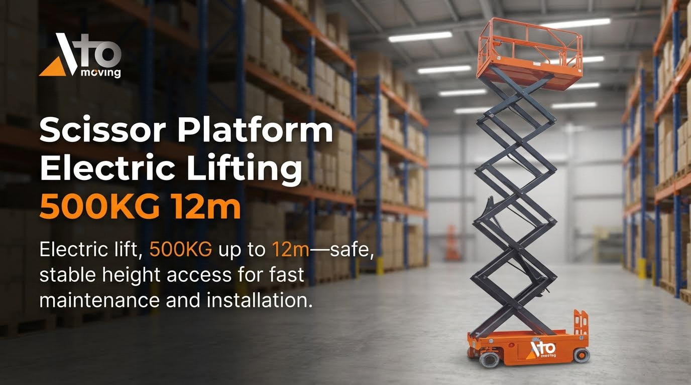
In practice, most industrial scissor lifts are designed with a structural safety factor of roughly 1.25–1.5 on static load and tested at 1.33× capacity, as noted above. That means a 500 kg rated platform has been structurally verified around 650–700 kg, but using that “extra” capacity in service removes the margin that keeps the lift stable under wind, braking, or operator motion.
Ground conditions, foundations, and stability criteria
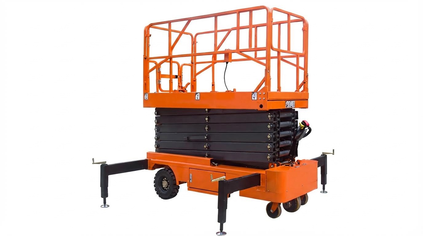
Even a perfectly designed scissor lift becomes unstable if the ground or foundation deforms or tilts. For mobile units, the “foundation” is simply the floor or ground beneath the wheels or outriggers; for fixed or in‑ground lifts, it is a reinforced concrete block designed to spread the load and resist cracking or settlement.
For permanent and in‑ground scissor lifts, foundation design is a major part of how stable are aerial platform over years of use. A typical specification for ultra‑thin surface‑mounted lifts calls for a reinforced concrete slab at least 160 mm thick, using concrete of at least C25 strength class. In‑ground pits often require 150 mm thick concrete on the bottom and side walls, with a 2–3% drainage slope and provisions for conduits and waterproofing in high‑groundwater areas. Surface flatness is also controlled tightly; a typical tolerance is ±3 mm over the lift footprint, verified with a laser level.
| Aspect | Typical requirement / practice | Stability impact |
|---|---|---|
| Concrete thickness (surface ultra‑thin lift) | ≥ 160 mm, C25 or higher concrete | Prevents punching and long‑term settlement under wheel loads |
| Concrete thickness (in‑ground pit) | ≈ 150 mm bottom and side walls | Provides rigid “box” to resist soil pressure and cracking |
| Surface flatness | Tolerance within about ±3 mm | Minimizes initial tilt and uneven leg loading |
| Drainage slope | 2–3% toward drain | Prevents water pooling and freeze‑thaw damage |
| Access clearances | Platform length ≈ 4.5 m, ≥ 1.6 m free space in front | Reduces collision risk and allows safe approach |
These construction details are not cosmetic; they directly control how the base resists tilting moments when the platform is raised and loaded. Accurate anchor‑bolt positioning and post‑pour curing (e.g., covering with plastic film for at least seven days) are standard practice before performing no‑load and full‑load tests to check for cracking or settlement.
- Never place mobile lifts on soft, deformable bases like loose fill, thick boards, or uncompacted soil.
- Check for hidden voids (trench covers, service ducts) under the wheelbase or outriggers.
- Use manufacturer‑approved outrigger pads or cribbing when working on asphalt or mixed ground.
- For indoor slabs, verify there are no major cracks, spalls, or level changes across the footprint.
Stability criteria in standards typically combine three checks: structural strength, deflection limits, and overturning resistance. The cited inspection standard requires whole‑machine stability to meet GB 25849‑2010, which defines allowable tilt angles and load combinations before tip‑over. In practice, this means a compliant lift on a flat, rigid foundation will remain upright with its rated load even when subjected to specified side loads and minor slopes, but only if the support surface itself does not yield.
Why soft or sloped ground is so risky
Scissor lifts have a relatively narrow base compared with their working height. On a slope, the COG moves toward the downhill edge; on soft ground, one wheel or outrigger can sink, which has the same geometric effect as adding slope. Because overturning moment grows with height, a small settlement at full elevation can consume the entire stability margin that standards assume.
Dynamic effects, wind, and operator movement
Static calculations explain only part of how stable are order picking machines; dynamic effects often drive real accidents. The lift structure and its load have natural frequencies, so horizontal or vertical motions near those frequencies can amplify sway and tilt. One study found that the fundamental natural frequencies of scissor lifts commonly fall between about 0.30 and 2.08 Hz, a range that overlaps with human body motion and wind‑induced oscillations. The same work noted that increased structural flexibility and higher ground slopes both reduce the tipping threshold.
Wind is a key dynamic load, especially for outdoor mobile platforms. Manufacturers specify maximum allowable wind speeds; exceeding these can produce side loads and oscillations that quickly erode stability, even if the platform is within its weight rating. Operators are advised to stop work during storms or strong gusts and to follow the wind limits in the manual. Because aerodynamic forces grow with height and exposed area, tall platforms with large guardrail‑mounted materials are particularly sensitive.
Operator and load movements also introduce dynamic effects. Sudden walking, jumping, or pushing against external structures can excite the lift’s natural frequencies. Research recommends avoiding continuous horizontal movement or vigorous actions by workers, especially when the lift is fully elevated or on less‑than‑ideal surfaces. Good practice is to treat a raised platform as a static workstation, not as a place for dynamic tasks like pulling hard on stuck components or using it as a lever against nearby structures.
- Do not drive or reposition mobile lifts at full height unless the manufacturer explicitly allows it and the surface is flat and firm.
- Avoid tying the platform to adjacent structures; this can transfer unexpected horizontal loads.
- Keep both feet on the platform floor; never climb guardrails to gain reach.
- Stop work and lower the platform if wind picks up or if noticeable sway develops.
Performance limits on speed are another way standards control dynamic loads. Typical inspection criteria cap lifting and lowering speeds at about 0.4 m/s, and travel speeds when elevated at or below 0.4 m/s (with up to 0.7 m/s allowed when the lift is fully lowered). These limits keep inertial forces within the stability margins assumed in design.
Putting dynamic limits into daily practice
From an engineering perspective, the safest operating pattern is: position the lift on firm, level ground; raise at controlled speed; perform work with minimal horizontal motion; then lower before relocating. Treat wind, bumps, and abrupt movements as “extra loads” that consume the same stability margin as additional weight or slope.
Operator Practices That Directly Influence Stability
Pre-use inspection, training, and safe controls use
Operator behavior is a primary answer to the question “how stable are scissor platform lifts” in real-world use. Even a well-designed lift can become unstable if inspections, training, and controls use are poor. Focus on repeatable routines and simple checklists so stability does not depend on luck.
- Conduct a structured pre-use walkaround
- Inspect for hydraulic leaks, damaged hoses, unusual noises, or jerky movements during a short function test Pre-Operation Inspection.
- Verify platform guardrails, access gates, and emergency stop controls operate correctly and latch securely Pre-Operation Inspection.
- Check tires or wheel units for damage and correct inflation where applicable Pre-Operation Inspection.
- Confirm battery charge or power supply status is adequate for the planned duty cycle Pre-Operation Inspection.
- Verify capacity and height limits before lifting
- Read the data plate and operating manual and respect rated platform capacity and maximum platform height Weight and Height Limits.
- Include people, tools, and materials in the load calculation, not just payload items.
- Stop operations and offload if alarms or overload indicators activate.
- Ensure only trained and authorized operators use the lift
- Provide formal training that covers controls layout, stability limits, weight management, and hazard recognition Operator Training.
- Limit operation to personnel who have been evaluated as competent for that specific lift type.
- Refresh training when site conditions, lift models, or regulations change.
- Test controls and brakes at the start of each shift
- Cycle all drive, lift, and steer functions slowly in a clear area to confirm correct response and direction Controls and Brakes.
- Verify service brakes and parking brakes hold the machine on the intended working slope within the manufacturer’s limits Controls and Brakes.
- Tag out the lift and report faults instead of “working around” sticky or delayed controls.
- Drill emergency procedures
- Train operators and ground spotters on the use of emergency stop and emergency lowering systems Emergency Preparedness.
- Keep rescue instructions and emergency contact numbers at the base controls.
- Practice lowering a raised platform under supervision so response is automatic in real events.
Why operator discipline matters for stability
Designers build in structural stability, but field stability depends heavily on the operator’s decisions. Overloading, skipping inspections, or misusing controls can shift the center of gravity outside the support polygon and cause tip risk, even on compliant equipment. Consistent pre-use checks and trained reactions are the fastest way to improve how stable are scissor platform lift on busy job sites.
Positioning, PPE, and working around site hazards
Where and how you position the machine has as much impact on stability as the lift design itself. Good positioning, correct PPE, and hazard awareness keep the platform within its safe envelope, even with wind and operator movement.
- Select and prepare a stable working surface
- Position the scissor lift on flat, firm, non-deformable ground; avoid soft soil, timber boards, or highly uneven surfaces that can settle or shift under load Recommandations pour surfaces et mouvements.
- Use outriggers or stabilizers where provided, and fully deploy them according to the manual Stabilization.
- Avoid operating near edges, pits, or trenches that could collapse under wheel loads.
- Control body movement and reach on the platform
- Keep both feet on the platform floor and avoid climbing or sitting on guardrails to gain extra reach Avoid Overreaching.
- Reposition the lift instead of leaning far outside the guardrail line.
- Reduce sudden horizontal movements or vigorous actions when fully elevated, because these can excite natural frequencies and increase tip risk Recommandations pour surfaces et mouvements.
- Use PPE that supports fall and impact protection
- Wear a hard hat to protect against overhead or falling objects in congested structures Personal Protective Equipment (PPE).
- Use a suitable harness and lanyard when required by company rules or local regulation, attaching only to approved anchor points on the platform Personal Protective Equipment (PPE).
- Wear non-slip footwear to maintain secure footing on possibly wet or dusty platform floors Personal Protective Equipment (PPE).
- Manage guardrails and access properly
- Close access gates or chains before raising the platform and keep them closed while elevated Guardrail Usage.
- Do not stand on mid-rails or top-rails; they are designed to restrain, not to be used as steps.
- Keep materials stacked below rail height so they cannot roll or slide over the edge.
- Survey and control the surrounding hazard zone
- Scan for overhead power lines, low beams, or ductwork and maintain safe clearances as specified by regulations Awareness of Surroundings.
- Keep a buffer from walls and fixed structures to avoid crushing hazards when driving or elevating near them Awareness of Surroundings.
- Control ground traffic around the base of the lift using barriers or spotters where necessary.
- Respect weather and wind limits
- Monitor site weather and never operate the lift during storms or strong gusts that could push the platform off-balance Weather Conditions.
- Follow the manufacturer’s maximum allowable wind speed for outdoor work, including gust factors.
- Consider wind sail area of cladding, panels, or signage being installed, not just the bare platform.
How positioning and PPE affect perceived stability
Operators often judge how stable are aerial platform by “feel” on the platform. Proper ground selection, controlled movement, and correct PPE reduce sway, slips, and fall potential, so the lift feels and remains more stable. This improves confidence, reduces fatigue, and cuts the likelihood of sudden corrective movements that can destabilize the structure.
Key Takeaways For Specifying And Operating Stable Lifts
Scissor lift stability results from matching sound engineering with disciplined operation. A wide, stiff chassis, well-proportioned scissor geometry, and a low center of gravity create the basic stability envelope. Hydraulics, mechanical locks, and structural stiffness then keep motion controlled and deflection low so the platform feels solid at height.
Load control and ground conditions decide how much of that engineered margin you actually keep. Respect the nameplate capacity, place loads near the platform center, and use only firm, level, non‑deformable surfaces or correctly designed concrete foundations. Standards that limit deflection, set overload test levels, and define minimum guardrail geometry all exist to keep the center of gravity inside the support polygon under real loads and minor slopes.
Dynamic effects and operator behavior often trigger incidents before pure strength limits do. Wind, sudden movement, or driving while elevated can quickly consume the remaining margin. Treat a raised platform as a static workstation, follow speed limits, and stop work when conditions change.
The best practice for engineering and operations teams is clear: select compliant Atomoving equipment, verify foundations and surfaces, enforce strict load and wind limits, and embed pre‑use inspection and training. When design, standards, and disciplined use align, scissor lifts deliver predictable, durable stability across their full working height.
Frequently Asked Questions
How stable are scissor lifts?
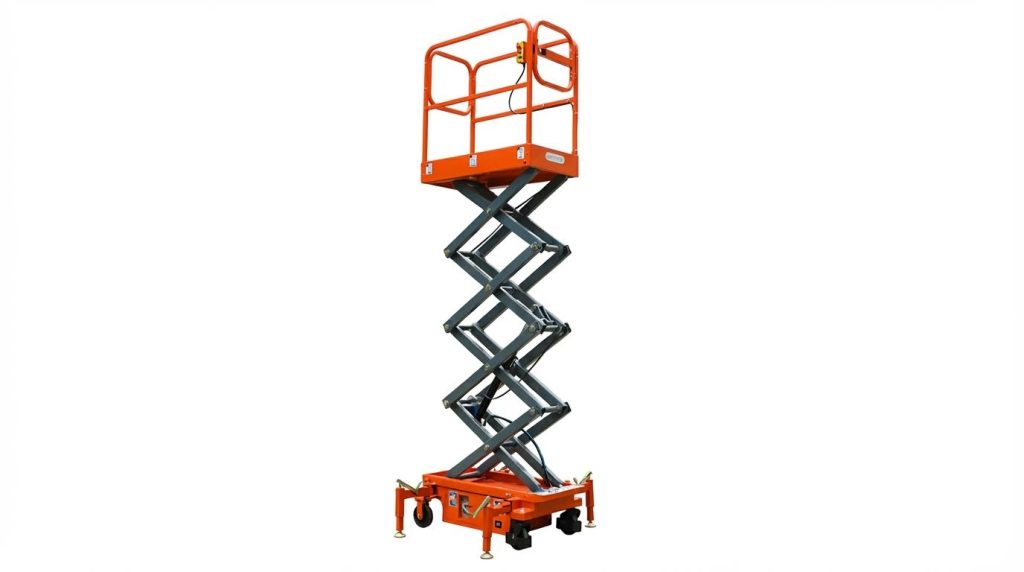
Scissor lifts are designed to be stable, especially when used on flat, even surfaces. They feature a larger platform supported by an “X”-shaped crisscross mechanism that extends vertically, providing a solid base for workers and tools. However, stability can be compromised by factors such as overloading, uneven terrain, or strong winds. Common Scissor Lift Mistakes.
- Avoid overloading the lift by checking and adhering to its load capacity.
- Use scissor lifts only on flat, level surfaces to maintain stability.
- Do not operate in windy conditions, especially if wind speeds exceed 25 mph. Scissor Lift Safety Tips.
What makes a scissor lift unstable?
Several factors can make a scissor lift unstable. Overloading the platform beyond its weight limit is one of the most common causes. Uneven or sloped surfaces can also affect balance, as can high winds or gusts. Proper training and adherence to safety guidelines can help prevent instability. Scissor Lift Stability Guide.
- Ensure the work surface is flat and free of obstacles.
- Monitor weather conditions and avoid use in high winds.
- Regularly inspect the equipment for wear and damage.