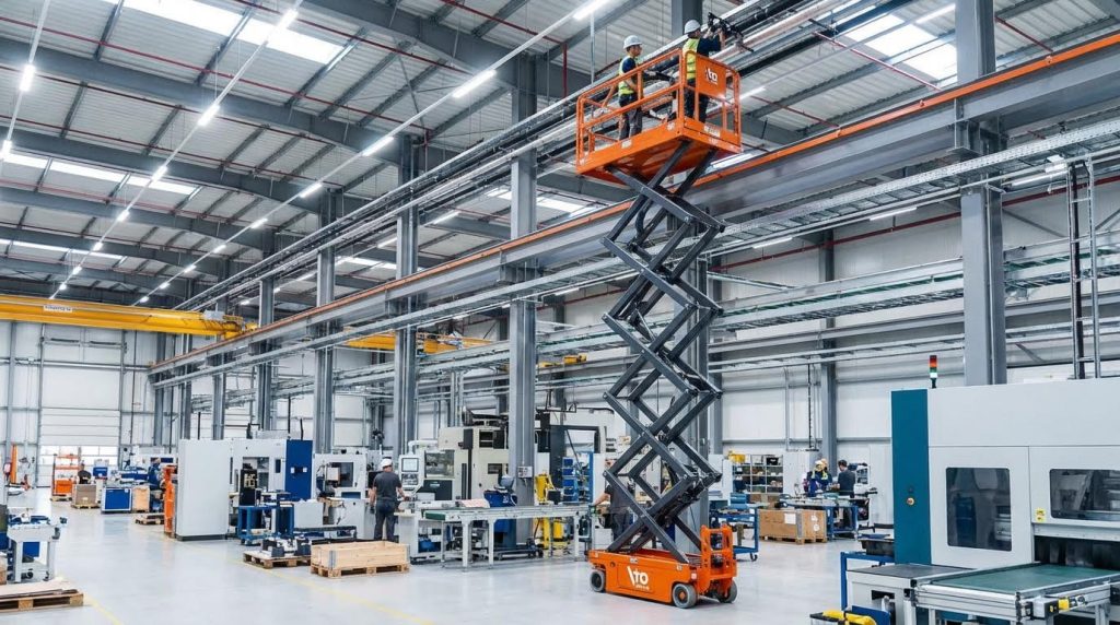
ระยะชักและระดับความสูงของแท่นยกแบบกรรไกรขึ้นอยู่กับความยาวของแขนและมุมที่กลไกสามารถเข้าถึงได้ ดังนั้นรูปทรงเรขาคณิตจึงเป็นตัวกำหนดทุกอย่าง ตั้งแต่ระยะการยกไปจนถึงขนาดของตัวขับเคลื่อน หากคุณต้องการทราบวิธีการคำนวณความสูงของแท่นยก แท่นกรรไกร เพื่อให้ถูกต้อง คุณต้องเชื่อมโยงตรีโกณมิติอย่างง่ายเข้ากับข้อจำกัดในโลกแห่งความเป็นจริง เช่น ความยาวของแท่น ความสูงเมื่อพับเก็บ และระยะการเคลื่อนที่ของตัวขับเคลื่อน คู่มือนี้จะอธิบายถึงรูปทรงเรขาคณิตที่จำเป็น สูตรคำนวณเชิงปฏิบัติ และข้อแลกเปลี่ยนในการออกแบบ เพื่อให้คุณสามารถคาดการณ์ความสูงในการยกได้ก่อนที่จะเริ่มตัดเหล็กใดๆ
เรขาคณิตพื้นฐานของการคำนวณความสูงของลิฟต์กรรไกร
ส่วนนี้จะอธิบายวิธีการคำนวณความสูงของ ลิฟท์กรรไกร โดยตรงจากความยาวแขนและมุมต่างๆ คุณจึงสามารถแปลงรูปทรงเรขาคณิตพื้นฐานให้เป็นความสูงของแท่นและระยะการเคลื่อนตัวที่เชื่อถือได้สำหรับการออกแบบจริงได้
กลไกการเคลื่อนที่แบบกรรไกรขั้นเดียวและมุมสำคัญ
ลิฟต์กรรไกรแบบขั้นเดียวแปลงการหมุนของแขนรอบจุดหมุนตรงกลางเป็นการเคลื่อนที่ในแนวดิ่งของแท่นโดยใช้ความสัมพันธ์ทางตรีโกณมิติอย่างง่ายระหว่างความยาวแขนและมุมเทียบกับแนวราบ
สำหรับกรรไกรแบบ X พื้นฐาน (แบบขั้นเดียว) ที่มีแขนเท่ากัน ระยะยกในแนวดิ่งจะขึ้นอยู่กับสามสิ่งหลักๆ ได้แก่ ความยาวของแขน มุมที่แต่ละแขนทำกับแนวราบ และมุมต่ำสุด/สูงสุดที่อนุญาตเพื่อความเสถียรและข้อจำกัดของแรง นี่คือหลักการทางเรขาคณิตหลักที่อยู่เบื้องหลังสูตรแรงและระยะชักส่วนใหญ่ที่ใช้ในโต๊ะยกอุตสาหกรรม เอกสารอ้างอิงสำหรับโครงสร้างสูตรทั่วไป.
| เทอมเรขาคณิต | สัญลักษณ์ | มันหมายถึงอะไร | ผลกระทบในการดำเนินงาน |
|---|---|---|---|
| ความยาวของแขน | แขนซ้าย | ระยะห่างจากจุดหมุนถึงจุดหมุนบนแท่งกรรไกรหนึ่งแท่ง | กำหนดมาตราส่วนพื้นฐานของระยะการเดินทางสูงสุดและขนาดชานชาลา |
| มุมกรรไกร (เทียบกับแนวนอน) | θ | มุมของแขนแต่ละข้างเทียบกับพื้น | ค่า θ ต่ำ = ความสูงต่ำ แต่แรงกระทำต่อตัวกระตุ้นสูงมาก; ค่า θ สูง = ความสูงสูง แรงงัดดีกว่า |
| มุมต่ำสุด | θ_min | มุมที่ตำแหน่งลดลงสุด | กำหนดความสูงที่ยุบตัวและแรงที่มากที่สุดในกรณีที่เลวร้ายที่สุด |
| มุมสูงสุด | θ_max | มุมที่ตำแหน่งยกขึ้นจนสุด | กำหนดความสูงสูงสุดของแท่นและระยะขอบความเสถียร |
| จังหวะของแพลตฟอร์ม | ∆H | ความแตกต่างระหว่างความสูงสูงสุดและต่ำสุดของแท่น | ต้องตรงตามข้อกำหนดด้านการยก เช่น ท่าเทียบสินค้า หรือสถานีทำงาน |
ในโต๊ะอุตสาหกรรมหลายๆ รุ่น รูปทรงทางเรขาคณิตที่ใช้งานได้จริงจะจำกัดมุมต่ำสุดไว้ที่ประมาณ 20–30° เพื่อหลีกเลี่ยงแรงกระทำจากตัวขับเคลื่อนที่มากเกินไป ในขณะที่ยังคงรักษาระดับความสูงเมื่อพับเก็บให้อยู่ในระดับที่เหมาะสม คำแนะนำทั่วไปเกี่ยวกับมุมและการเคลื่อนที่.
- การเลือกมุมที่สำคัญ: รักษาค่า θ_min ให้อยู่เหนือ ~20° – ช่วยลดแรงกระแทกมหาศาลจากอุปกรณ์ขับเคลื่อนที่ระดับพื้น
- แขนสมมาตร: ใช้แขนที่มีความยาวเท่ากันรอบจุดหมุนตรงกลาง – ช่วยลดความซับซ้อนของการคำนวณจลศาสตร์และแรง
- จุดหมุนที่แข็ง: ออกแบบจุดหมุนที่มีระยะการเคลื่อนที่น้อย – ช่วยลดการเคลื่อนไหวในแนวด้านข้างเมื่ออยู่ในมุมสูง
- มุมหยุด: เพิ่มจุดหยุดตายตัวสำหรับ θ_max – ป้องกันการยืดมากเกินไปและการสูญเสียเสถียรภาพ
💡 หมายเหตุจากวิศวกรภาคสนาม: เมื่อคุณจำลองกรรไกรที่มุมต่ำมาก คณิตศาสตร์อาจบอกว่ามันยังยกได้ แต่ในสนามจริง ตัวขับเคลื่อน หมุด และความเรียบของพื้นมักจะเป็นตัวจำกัดก่อนเสมอ ตรวจสอบค่า θ_min ที่ต่ำกว่า 20° ด้วยแบบจำลองขนาดเต็มหรือการตรวจสอบแรงแบบอนุรักษ์นิยมเสมอ
มุมมีผลต่อแรงและความเสถียรอย่างไร
เมื่อ θ เข้าใกล้ศูนย์ ค่า sin(θ) ในสมการแรงจะน้อยลงมาก ดังนั้นแรงที่ต้องการจากตัวกระตุ้นจึงเพิ่มขึ้นอย่างรวดเร็ว ที่ค่า θ สูงขึ้น แรงยกจะ "แข็ง" ขึ้นในแนวตั้ง ซึ่งช่วยเพิ่มเสถียรภาพ แต่ก็ทำให้แรงด้านข้างที่กระทำต่อจุดหมุนเพิ่มมากขึ้นด้วย
ความสัมพันธ์ระหว่างความยาวแขนกับระยะการเหวี่ยงและความสูงของแท่น
ความยาวแขนและช่วงมุมกำหนดวิธีการคำนวณความสูง ลิฟท์กรรไกรซึ่งจะช่วยให้คุณได้สูตรโดยตรงในการแปลงระยะการเคลื่อนที่ของแท่นที่ต้องการ ให้เป็นความยาวและมุมการตัดที่ต้องการ
ระยะการเคลื่อนที่ (แนวตั้ง) ของลิฟต์กรรไกรจะแปรผันเกือบเป็นเส้นตรงกับความยาวของแขนในช่วงมุมที่กำหนด ซึ่งเป็นเหตุผลว่าทำไมการเลือกขนาดเบื้องต้นจึงมักเริ่มต้นจากความยาวของแขน คำแนะนำเชิงปฏิบัติจากลิฟต์ขนาดเล็กในโรงงานแสดงให้เห็นว่าแขนยาว 0.91 เมตร ให้ระยะการเคลื่อนที่ประมาณ 0.76 เมตร ในขณะที่แขนยาว 0.61 เมตร ให้ระยะการเคลื่อนที่ประมาณ 0.51 เมตร โดยความสัมพันธ์จะแปรผันตามรูปทรงเรขาคณิต ตัวอย่างข้อมูลความยาวแขนเทียบกับระยะการเคลื่อนที่.
| ตัวอย่างความยาวแขน (โดยประมาณ) | การเคลื่อนที่ในแนวดิ่งโดยทั่วไป | การเดินทาง ÷ ความยาวช่วงแขน | ดีที่สุดสำหรับ… |
|---|---|---|---|
| 610 มม | ≈ 510 มม | ≈ 0.84 | ม้านั่งขนาดกะทัดรัดและโต๊ะวางเครื่องมือขนาดเล็ก |
| 910 มม | ≈ 760 มม | ≈ 0.84 | แท่นทำงานขนาดกลางและโต๊ะยก |
แนวทางปฏิบัติทางอุตสาหกรรมบางส่วนยังใช้กฎแบบง่ายๆ ที่มุม 45° โดยที่ระยะชักที่มีประสิทธิภาพโดยประมาณคือ ความยาวแขน × sin(45°) แขนยาว 1,000 มม. จะให้ระยะชักที่มีประสิทธิภาพประมาณ 707 มม. และเพื่อให้ได้ระยะชัก 2,000 มม. จำเป็นต้องใช้แขนกรรไกรที่มีความยาวประมาณ 2,830 มม. ตัวอย่างการกำหนดขนาดเส้นและความยาว.
| จังหวะเป้าหมาย | ความยาวกรรไกรโดยประมาณ | พื้นฐานทางเรขาคณิตอย่างง่าย | ผลกระทบในการดำเนินงาน |
|---|---|---|---|
| ≈ 700 มม | 1,000 มม | L_arm × sin(45°) | เหมาะสำหรับเวิร์กสเตชันแบบกรรไกรเดี่ยว |
| 2,000 มม | ≈ 2,830 มม | สโตรก / sin(45°) | จำเป็นต้องใช้แขนยาวหรือการออกแบบหลายขั้นตอน |
- กฎทั่วไปคือความยาวช่วงแขน: แขนที่ยาวขึ้นจะทำให้ระยะการเคลื่อนที่เพิ่มขึ้นเกือบเป็นสัดส่วนโดยตรง – เหมาะสำหรับใช้ในการกำหนดขนาดเบื้องต้นก่อนการออกแบบ CAD อย่างละเอียด
- หน้าต่างมุม: เลือกค่า θ_min และ θ_max ก่อน – จากนั้นคำนวณย้อนกลับหาความยาวแขนและระยะชักของตัวกระตุ้น
- ความยาวของส้นรองเท้าเทียบกับความยาวของกรรไกร: ควรให้แท่นวางยาวกว่าส่วนกรรไกร – เว้นพื้นที่ไว้สำหรับขอบนิรภัยและระยะการเคลื่อนที่เกินกำหนด
คำแนะนำทางอุตสาหกรรมระบุว่า ความยาวของแท่นวางต้องยาวกว่าความยาวของกรรไกรประมาณ 150 มิลลิเมตร เพื่อรองรับอุปกรณ์และคุณสมบัติด้านความปลอดภัย ดังนั้นกรรไกรที่มีความยาว 2,830 มิลลิเมตร จึงต้องการแท่นวางที่มีความยาวอย่างน้อย 2,980 มิลลิเมตร ตัวอย่างการอนุญาตความยาวของชานชาลา.
ขั้นตอนการทำงานง่ายๆ ในการคำนวณความยาวแขนที่ต้องการ
1) กำหนดระยะการเคลื่อนที่ของแท่นที่ต้องการ (ΔH) 2) ตัดสินใจเลือกค่า θ_min และ θ_max ที่ยอมรับได้ โดยพิจารณาจากแรงและความเสถียร 3) ใช้ค่าอัตราส่วนตัวอย่าง (ระยะการเคลื่อนที่ ≈ 0.8–0.9 × L_arm) หรือตรีโกณมิติโดยละเอียดเพื่อประมาณค่า L_arm 4) ตรวจสอบว่าความยาวของแท่นและระดับความลึกของหลุมที่ได้นั้นใช้งานได้จริง
💡 หมายเหตุจากวิศวกรภาคสนาม: เมื่อคุณพยายามยืดแขนยาวๆ เพื่อตีจังหวะสูงในครั้งเดียว ให้สังเกตระยะยื่นของแท่นและระดับความเรียบของพื้น แขนที่ยาวและเรียวจะทำให้การบิดตัวของฐานเพิ่มมากขึ้น และอาจทำให้เกิดการติดขัดหรือการยกที่ไม่สม่ำเสมอหากพื้นไม่เรียบแม้เพียงไม่กี่มิลลิเมตร
ความสัมพันธ์โดยละเอียดระหว่างจังหวะการลากและแรง
ส่วนนี้จะอธิบายวิธีการคำนวณความสูงของ ลิฟท์กรรไกรโดยใช้ตรีโกณมิติอย่างง่ายในการคำนวณระยะชักของตัวกระตุ้นและแรงที่ต้องการ เพื่อให้คุณสามารถเลือกขนาดแขนและกระบอกสูบได้อย่างถูกต้อง และหลีกเลี่ยงการรับน้ำหนักเกินที่ระดับความสูงในการยกต่ำ
เป้าหมายคือการเชื่อมโยงสามสิ่งเข้าด้วยกัน ได้แก่ รูปทรงของแขนกล ระยะการเคลื่อนที่ของแท่น และภาระของตัวขับเคลื่อน เมื่อคุณเข้าใจความสัมพันธ์เหล่านี้แล้ว คุณจะสามารถคาดการณ์ความสูงในการยก เลือกความยาวของแขนกล และระบุตัวขับเคลื่อนที่เหมาะสมซึ่งมีระยะการเคลื่อนที่และแรงสำรองที่เพียงพอได้
สูตรตรีโกณมิติสำหรับระยะยก
สูตรตรีโกณมิติอธิบายว่าความยาวและมุมของแขนสร้างระยะยกในแนวดิ่งได้อย่างไร ซึ่งเป็นพื้นฐานของการคำนวณความสูงของวัตถุ ลิฟท์กรรไกร จากเรขาคณิตพื้นฐาน
สำหรับแท่นกรรไกรเดี่ยวที่มีความยาวแขนยาว Lแขน (จากจุดหมุนถึงจุดหมุน) และมุมแขน θ วัดจากแนวนอน การมีส่วนร่วมแนวตั้งของแขนข้างหนึ่งคือ Lแขน·sin(θ) เมื่อใช้กลไกกรรไกรไขว้แบบมาตรฐาน แรงยกในแนวดิ่งของแท่นจะอยู่ที่ประมาณสองเท่า หักลบด้วยค่าเบี่ยงเบนเล็กน้อยจากจุดหมุนและโครงสร้าง
| พารามิเตอร์ | สัญลักษณ์ / สูตรทั่วไป | ความหมาย | ผลกระทบในการดำเนินงาน |
|---|---|---|---|
| ความยาวของแขน | Lแขน | ระยะห่างระหว่างจุดหมุนหลักของแขนข้างหนึ่ง | กำหนดระยะการเดินทางสูงสุดตามทฤษฎี |
| มุมกรรไกร (จากแนวนอน) | θ | 0° = แนวราบ, 90° = แนวตั้ง | ค่า θ ต่ำจะทำให้ได้แรงงัดน้อยและแรงสูง |
| การเคลื่อนที่ขึ้นลงในแนวดิ่งของแพลตฟอร์ม (ขั้นเดียว) | ≈ 2·ลิตรแขน·(sin θแม็กซ์ − ซิน θนาที) | การเปลี่ยนแปลงความสูงของชานชาลา | สูตรหลักในการประมาณระยะยกของลิฟต์ |
| ระยะชักที่มีประสิทธิภาพที่มุม 45° | ≈ Lแขน·ไซน์ 45° | ตัวอย่างการลดรูป | ใช้สำหรับตรวจสอบขนาดอย่างรวดเร็ว สำหรับโต๊ะยก |
ตัวอย่างการใช้งานจริงอย่างหนึ่งใช้ความสัมพันธ์แบบง่ายๆ ว่า “ระยะชักที่มีประสิทธิภาพ ≈ ความยาวกรรไกร × sin 45°” สำหรับแขนยาว 1,000 มม. จะได้ระยะการเคลื่อนที่ประมาณ 707 มม. หากต้องการระยะการเคลื่อนที่ 2,000 มม. จะต้องใช้แขนยาวประมาณ 2,830 มม. ความสัมพันธ์นี้ถูกนำมาใช้กันอย่างแพร่หลายในการกำหนดขนาดโต๊ะยก.
อีกวิธีหนึ่งในการแสดงรูปทรงเรขาคณิตจะเน้นที่ระยะการเคลื่อนที่ของตัวกระตุ้นเทียบกับมุมกรรไกร สำหรับตัวกระตุ้นแนวนอนทั่วไประหว่างชิ้นส่วนกรรไกร ระยะการเคลื่อนที่ของแท่นแนวตั้งจะสัมพันธ์กับความยาวแขนและช่วงมุมโดย: ระยะการเคลื่อนที่เวที ≈ 2·ลิตรแขน·(sin θแม็กซ์ − ซิน θนาทีนี่คือจุดเริ่มต้นที่ชัดเจนที่สุดเมื่อคุณต้องการคำนวณความสูงของแท่นจากรูปทรงเรขาคณิตของแขน
เรื่องนี้เกี่ยวข้องกับ “วิธีการคำนวณความสูงของลิฟต์กรรไกร” อย่างไร
ในการคำนวณความสูงสูงสุด: เลือก Lแขนกำหนดมุมที่ปลอดภัยต่ำสุดและสูงสุดของคุณ (ตัวอย่างเช่น 20° ถึง 70°) จากนั้นใช้ Hแม็กซ์ ≈ ความสูงฐาน + 2·Lแขน·sin θแม็กซ์ลบ 2 ลิตรแขน·sin θนาที เพื่อให้ได้การเดินทางสุทธิ
💡 หมายเหตุจากวิศวกรภาคสนาม: เมื่อจำลองการเคลื่อนที่ด้วยตรีโกณมิติในอุดมคติ ให้หักระยะการเคลื่อนที่ตามทฤษฎีในเครื่องจักรจริงออก 50–150 มม. เสมอ สำหรับระยะห่างของจุดหมุน โครงสร้างแท่น และตัวหยุดเชิงกล มิเช่นนั้นลิฟต์จะไม่สามารถยกขึ้นไปถึงความสูง "ตามแบบ" ได้
ระยะการเคลื่อนที่ของตัวกระตุ้นเทียบกับระยะการเคลื่อนที่ของแท่น
ระยะการเคลื่อนที่ของตัวขับเคลื่อนจะสั้นกว่าระยะการเคลื่อนที่ของแท่นเสมอ ดังนั้นคุณต้องแปลงความสูงในการยกที่ต้องการให้เป็นการยืดตัวของตัวขับเคลื่อนโดยใช้รูปทรงเรขาคณิตแบบกรรไกรเฉพาะ
สำหรับโครงสร้างทั่วไปที่มีทรงกระบอกแนวนอนอยู่ระหว่างชิ้นส่วนกรรไกรด้านล่างและด้านบน ความสัมพันธ์ที่ใช้กันอย่างแพร่หลายคือ: ระยะชักตัวกระตุ้น = 2·ลิตรแขน·(cos θนาที − cos θแม็กซ์). สิ่งนี้เกิดขึ้นโดยตรงจากการเปลี่ยนแปลงการฉายภาพความยาวแขน.
| อินพุตการออกแบบ | ใช้ในการคำนวณ | ค่าที่ได้ | ดีที่สุดสำหรับ… |
|---|---|---|---|
| การเดินทางด้วยชานชาลาที่ต้องการ H | เลือก θนาที, θแม็กซ์แก้สมการ H ≈ 2·Lแขน·(sin θแม็กซ์ − ซิน θนาที) | ต้องใช้ Lแขน | การกำหนดขนาดทางเรขาคณิตในระยะเริ่มต้น |
| ความยาวแขนที่เลือกคือไซส์ Lแขน | ใช้จังหวะกระทำ = 2·ลิตรแขน·(cos θนาที − cos θแม็กซ์) | ระยะการเคลื่อนที่ของแอคชูเอเตอร์ในหน่วยมิลลิเมตร | เลือกใช้กระบอกสูบหรือแอคทูเอเตอร์เชิงเส้น |
| ระยะชักของแอคชูเอเตอร์ที่มีอยู่ | จัดเรียงใหม่เพื่อหาช่วงค่า θ ที่เป็นไปได้ | ความสูงสูงสุดที่สามารถทำได้ | การปรับปรุงลิฟต์เก่าโดยไม่ต้องเปลี่ยนแขนลิฟต์ |
ในทางปฏิบัติ ระยะการเคลื่อนที่ของแอคชูเอเตอร์ต้องมากกว่าข้อกำหนดทางเรขาคณิตประมาณ 10-15% เพื่อให้มีพื้นที่สำหรับความคลาดเคลื่อนในการติดตั้งและการรองรับแรงกระแทกเมื่อสิ้นสุดระยะการเคลื่อนที่ คู่มือปฏิบัติแนะนำให้เผื่อระยะขอบเพิ่มเติมนี้ ดังนั้นลิฟต์จึงไม่ชนกับขีดจำกัดของแอคชูเอเตอร์อย่างรุนแรง
แรงที่กระทำต่อแอคทูเอเตอร์ก็แปรผันอย่างมากตามมุมเช่นกัน เอกสารอ้างอิงฉบับหนึ่งระบุว่า Fตัวกระตุ้น = (W·Lเวที)/(2·ลิตรตัวกระตุ้น·sin θ) โดยที่ W คือภาระรวม Lเวที คือระยะทางในแนวนอนจากจุดศูนย์กลางของแรงไปยังจุดหมุน และ θ คือมุมของแขนจากแนวนอน เมื่อ θ เข้าใกล้ศูนย์ ค่า sin θ จะมีค่าเล็กน้อย และแรงจะเพิ่มขึ้นอย่างรวดเร็ว.
- มุมต่ำ (ใกล้พังทลาย): แรงขับสูงสุดของแอคทูเอเตอร์ – มีความสำคัญอย่างยิ่งต่อการกำหนดขนาดรูเจาะหรือแรงบิดของมอเตอร์
- ช่วงกลางจังหวะ: แรงจะลดลงเมื่อค่า sin θ เพิ่มขึ้น – ภูมิภาคปฏิบัติการที่มีประสิทธิภาพสูงสุด
- ความสูงเกือบเต็ม: แรงต่ำสุด – แต่ความมั่นคงและการแกว่งตัวกลับมีความสำคัญมากขึ้น
ขั้นตอนการออกแบบอย่างรวดเร็ว ตั้งแต่ความสูงไปจนถึงระยะการเคลื่อนที่ของกลไกขับเคลื่อน
1) กำหนดระยะการเคลื่อนที่ของแท่น H และความสูงของฐานที่ต้องการ 2) เลือกค่า θ ที่ปลอดภัยนาที (โดยทั่วไป 15–20°) และ θแม็กซ์ (60–70°) 3) แก้หาค่า Lแขน จาก H ≈ 2·Lแขน·(sin θแม็กซ์ − ซิน θนาที) 4) คำนวณระยะชักของแอคทูเอเตอร์จาก Strokeกระทำ = 2·ลิตรแขน·(cos θนาที − cos θแม็กซ์5) เพิ่มระยะเผื่อ 10–15% และเลือกแอคชูเอเตอร์แบบมาตรฐาน
💡 หมายเหตุจากวิศวกรภาคสนาม: เมื่อคุณกด θนาที หากมุม θ อยู่ใกล้ระนาบมากเกินไป จะทำให้ความสูงเพิ่มขึ้น แรงกระทำของตัวกระตุ้น และแรงด้านข้างบนจุดหมุนจะพุ่งสูงขึ้น ในโรงงาน ผมแทบจะไม่ยอมให้มีมุม θ เลยนาที อุณหภูมิต่ำกว่า 15–20° เพื่ออายุการใช้งานที่ยาวนานและขนาดกระบอกสูบที่เหมาะสม
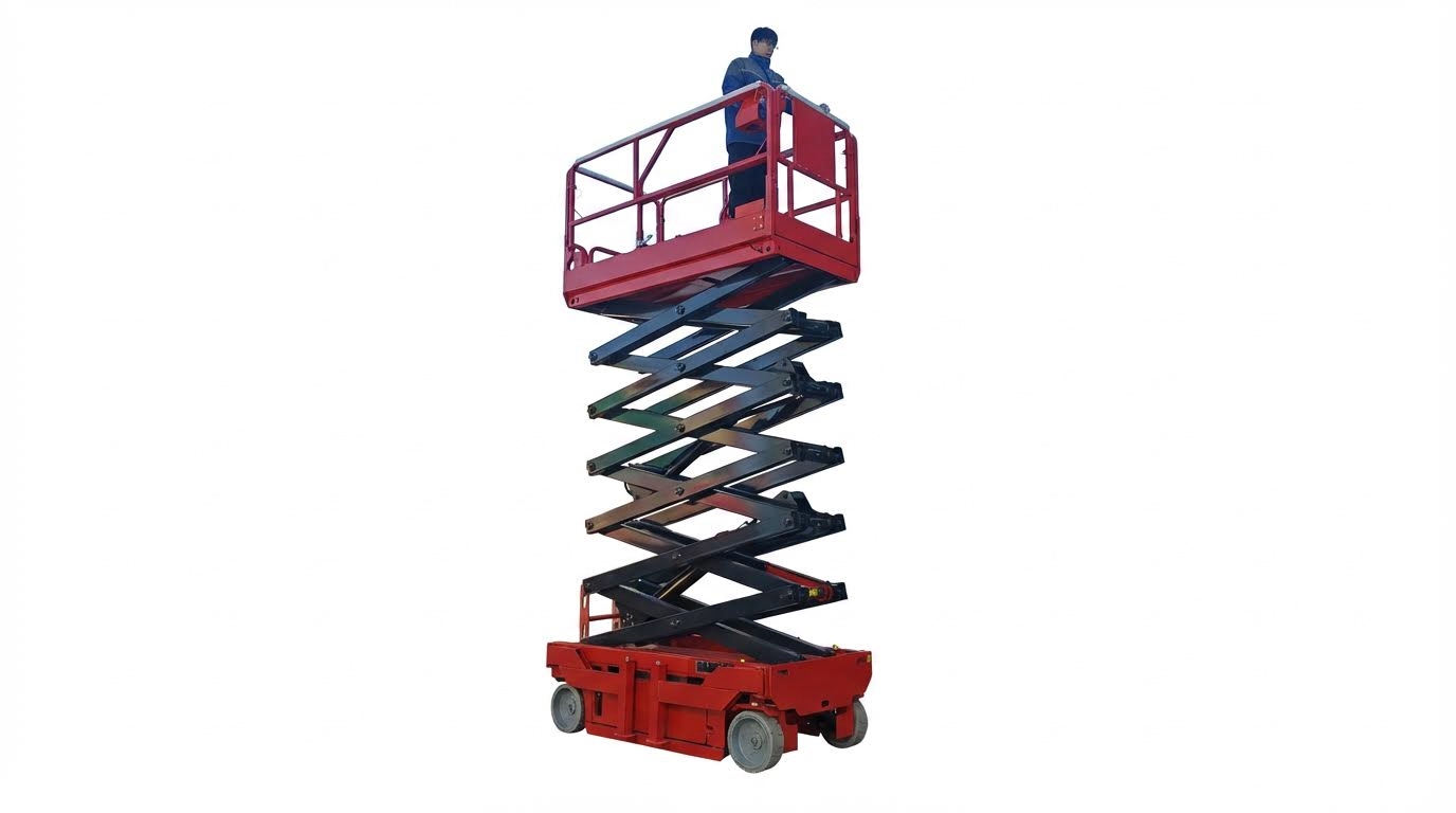
ผลของกรรไกรหลายขั้นตอนต่อความสูงและแรง
ชุดกลไกกรรไกรหลายขั้นตอนช่วยเพิ่มความสูงและระยะการเคลื่อนที่โดยไม่เปลี่ยนแปลงระดับแรงพื้นฐานอย่างมาก แต่ต้องการระยะการเคลื่อนที่ของตัวกระตุ้นที่มากขึ้นและการควบคุมเสถียรภาพอย่างระมัดระวัง
สำหรับกลไกกรรไกรคู่ แท่นสองแท่นที่เหมือนกันจะซ้อนกันในแนวตั้ง ระยะการเคลื่อนที่ของแท่นจะมากกว่ากลไกแท่นเดี่ยวประมาณสองเท่า สำหรับความยาวแขนและช่วงมุมเดียวกัน แต่แรงขับเคลื่อนจะยังคงใกล้เคียงกัน หากตัวขับเคลื่อนยังคงขับเคลื่อนเฉพาะแท่นด้านล่างเท่านั้น ข้อมูลจากอุตสาหกรรมระบุว่า โต๊ะเลื่อยกรรไกรคู่ให้ระยะชักประมาณสองเท่า เมื่อเทียบกับกรรไกรเดี่ยว
| องค์ประกอบ | ระยะชักของแท่นโดยประมาณ | ระดับแรงของแอคชูเอเตอร์ | ผลกระทบในการดำเนินงาน |
|---|---|---|---|
| กรรไกรเดี่ยว | H ≈ 2·Lแขน·(sin θแม็กซ์ − ซิน θนาที) | baseline | เหมาะสำหรับความสูงในการยกต่ำถึงปานกลาง และความลึกของหลุมน้อยที่สุด |
| กรรไกรคู่ | ≈ 2 เท่าของระยะชักแบบขั้นตอนเดียว | ≈ คล้ายกับแบบขั้นเดียวสำหรับโหลดเดียวกัน | สามารถขยายพื้นที่ได้สูงขึ้นด้วยขนาดพื้นที่เท่าเดิม แต่ต้องใช้หลุมที่ลึกกว่าหรือความสูงเมื่อยุบตัวที่มากกว่า ในการติดตั้งระดับพื้น |
| ขั้นตอนการตัดหลายขั้นตอน (3–5) | ประมาณ 3–5 เท่าของระยะชักเดียว | ในแต่ละขั้นตอนมีความคล้ายคลึงกัน แต่โครงสร้างมีโมเมนต์ที่สูงกว่า | ใช้ในกรณีที่ต้องการยกของหนักมากโดยไม่ต้องใช้เสาสูง ความเสถียรและการแกว่งตัวจึงมีความสำคัญอย่างยิ่ง |
เอกสารอ้างอิงทางวิศวกรรมฉบับหนึ่งอธิบายว่า กรรไกรคู่ “ต้องการแรงขับเคลื่อนที่ใกล้เคียงกับกรรไกรเดี่ยวเพื่อให้ได้ความสามารถในการรับน้ำหนักที่เท่ากัน แต่ต้องการระยะชักประมาณสองเท่าเพื่อให้ได้ความสูงที่เพิ่มขึ้นเท่ากัน” ด้วยเหตุนี้ ระยะการเคลื่อนที่ของแอคชูเอเตอร์จึงมักกลายเป็นปัจจัยจำกัดในการออกแบบแบบหลายขั้นตอน.
- เวทีเพิ่มเติม: เพิ่มความสูงโดยที่ความยาวแขนเท่าเดิม – เหมาะสำหรับพื้นที่ที่มีจำกัด
- แรงกระทำเท่ากัน: ชั้นล่างสุดยังคงรับน้ำหนักอยู่ – กราฟแรงมีลักษณะคล้ายกับแบบขั้นตอนเดียว
- ระยะชักของแอคชูเอเตอร์ที่ยาวขึ้น: ต้องใช้จังหวะการตีประมาณ N ครั้ง สำหรับ N ขั้นตอน – อาจผลักดันให้คุณเลือกใช้ระบบไฮดรอลิกแทนระบบไฟฟ้า
เมื่อใดควรเลือกใช้แขนแบบหลายขั้นตอนหรือแบบยาว
ใช้แขนยกที่ยาวขึ้นหากคุณมีพื้นที่สำหรับแท่นยกที่ยาวขึ้นและต้องการกลไกที่เรียบง่ายกว่า เปลี่ยนไปใช้แขนยกแบบกรรไกรคู่หรือสามแขนเมื่อความยาวของแท่นยกมีจำกัด ความลึกของหลุมมีจำกัด หรือคุณต้องการยกสูงมาก (เช่น 3–6 เมตร) ในพื้นที่ขนาดกะทัดรัด
💡 หมายเหตุจากวิศวกรภาคสนาม: สำหรับลิฟต์หลายขั้นที่สูงชัน รูปทรงอาจ "ใช้งานได้" บนกระดาษ แต่ความแข็งแกร่งด้านข้างมักเป็นตัวกำหนดการออกแบบ ผมมักจะเพิ่มขนาดส่วนแขนและจุดหมุนให้ใหญ่กว่าที่คำนวณความแข็งแรงไว้ เพื่อควบคุมการแกว่งเมื่อยืดออกจนสุด
ทางเลือกในการออกแบบสำหรับการใช้งานในอุตสาหกรรม
การออกแบบลิฟต์กรรไกรอุตสาหกรรมนั้นต้องคำนึงถึงความสมดุลระหว่างรูปทรงเรขาคณิต ความสามารถของกลไกขับเคลื่อน และความปลอดภัย เพื่อให้ได้ความสูงที่ต้องการด้วยแรง ขนาดพื้นที่ และรอบการทำงานที่ยอมรับได้ นี่คือจุดที่คุณจะเปลี่ยนคำถามที่ว่า “วิธีการคำนวณความสูงของลิฟต์กรรไกร” ให้กลายเป็นเครื่องจักรที่สามารถสร้างได้จริงและเชื่อถือได้
การเลือกความยาวแขน ขนาดแท่นวาง และความสูงเมื่อพับเก็บ
การเลือกความยาวแขน ขนาดแท่น และความสูงเมื่อพับเก็บ เริ่มต้นจากระยะการเคลื่อนที่ที่ต้องการ จากนั้นจึงคำนวณย้อนกลับความยาวกรรไกรและขอบเขตของแท่นจากรูปทรงเรขาคณิตของกลไกเชื่อมต่อและข้อจำกัดของพื้นที่ติดตั้ง
- เริ่มต้นจากจังหวะการตีที่ต้องการ: กำหนดความสูงของแท่นขั้นต่ำและสูงสุด – นี่คือหลักการสำคัญในการคำนวณความสูงของลิฟต์กรรไกรสำหรับงานของคุณ
- ความสัมพันธ์ระหว่างจังหวะการตีกับความยาวของแขน: ใช้ความยาวแขนและช่วงมุมเพื่อประมาณระยะทางที่เคลื่อนที่ – ช่วยให้มั่นใจได้ว่าข้อต่อสามารถเข้าถึงความสูงเป้าหมายได้จริง
- ตรวจสอบความยาวของแพลตฟอร์มเทียบกับความยาวของกรรไกร: แท่นวางต้องยาวกว่าความยาวของกรรไกร – ช่วยป้องกันไม่ให้แขนยื่นออกมา และเว้นพื้นที่สำหรับขอบเพื่อความปลอดภัย
- ควบคุมความสูงเมื่อยุบตัว: จำกัดมุมขั้นต่ำหรือใช้แบบหลายขั้นตอน – เหมาะสำหรับหลุมตื้นหรือระดับการรับ/ส่งน้ำหนักต่ำ
- ปรับเปลี่ยนรูปทรงเรขาคณิตของแอคทูเอเตอร์: ความยาวของแขนและช่วงมุมต้องสอดคล้องกับระยะการเคลื่อนที่ของตัวกระตุ้นที่สามารถทำได้จริง – หลีกเลี่ยงข้อกำหนดเกี่ยวกับกระบอกสูบที่ไม่สามารถทำได้จริง
จากรูปทรงเรขาคณิต วิธีการทางวิศวกรรมทั่วไปคือการเริ่มต้นด้วยระยะชักที่มีประสิทธิภาพโดยประมาณของกรรไกรแบบขั้นเดียวเป็นเศษส่วนของความยาวแขน เอกสารอ้างอิงหนึ่งใช้ระยะชักที่มีประสิทธิภาพประมาณ sin(45°) ของความยาวแขนสำหรับโครงสร้างอุตสาหกรรมทั่วไป ดังนั้น ระยะชักที่มีประสิทธิภาพ ≈ L_scissor × 0.707 สำหรับโต๊ะยกทั่วไปนั่นหมายความว่า แขนยาว 1,000 มม. จะให้ระยะยกที่ใช้งานได้ประมาณ 700 มม. ภายในขอบเขตการออกแบบที่เหมาะสม
| เป้าหมายการออกแบบ | ความสัมพันธ์/กฎทั่วไป | ผลกระทบในการดำเนินงาน |
|---|---|---|
| ระยะชักของแท่นที่ต้องการ | ตั้งค่าความสูงในการทำงานต่ำสุด/สูงสุด (เช่น 0.3 ม. ถึง 1.3 ม. → ระยะชัก 1.0 ม.) | กำหนดขนาดโดยรวมของกลไกและระยะการเคลื่อนที่ของตัวกระตุ้น |
| ความยาวของแขนกรรไกร | ระยะชักที่มีประสิทธิภาพ ≈ 0.7 เท่าของความยาวแขน สำหรับรูปแบบทั่วไป อ้างอิงจาก sin(45°) | ระยะชัก 1.0 เมตร → ความยาวแขน ≈ 1.4 เมตร |
| ความยาวของแพลตฟอร์มเทียบกับความยาวของแขน | ความยาวของแท่นวางต้องยาวกว่าความยาวของกรรไกร ให้เผื่อไว้ประมาณ 150 มม. สำหรับขอบเพื่อความปลอดภัย | ช่วยให้มีพื้นที่สำหรับแผ่นกันกระแทกและขอบรองเท้า |
| ตัวอย่าง: ระยะชัก 2,000 มม. | ความยาวกรรไกร ≈ 2,830 มม.; แท่นวาง ≥ 2,980 มม. คำแนะนำทั่วไป | เหมาะสำหรับพาเลทมาตรฐานที่มีระยะเผื่อเพื่อความปลอดภัย |
| ขีดจำกัดความสูงที่ยุบตัวลง | ตั้งค่าโดยมุมกรรไกรขั้นต่ำและความลึกของแขน | กำหนดความลึกของหลุมหรือความสูงของทางลาดขนถ่าย |
ตัวอย่างการใช้งาน: วิธีคำนวณความสูงของลิฟต์กรรไกรจากความยาวแขน
สมมติว่าคุณเลือกความยาวแขน L_arm = 1,400 มม. และใช้งานโดยปรับมุมประมาณ 20° ถึง 70° จากแนวราบเพื่อความเสถียร ความสัมพันธ์ทางเรขาคณิตที่ละเอียดกว่าสำหรับกรรไกรเดี่ยวจะให้ค่าการยกในแนวดิ่ง ≈ L_arm × (sin(θ_max) – sin(θ_min)) โดยที่ θ_min ≈ 20° และ θ_max ≈ 70° จะได้ค่าการยกประมาณ 1,400 มม. × (0.94 – 0.34) ≈ 840 มม. หากคุณต้องการระยะการยก 1,000 มม. คุณอาจต้องเพิ่มความยาวของแขน เพิ่มช่วงมุม (หากความเสถียรเอื้ออำนวย) หรือเปลี่ยนไปใช้กรรไกรคู่ นี่คือแนวทางปฏิบัติจากตัวเลือกความยาวแขนและมุม ไปสู่ "ความสูง" ที่แท่นสามารถยกได้
💡 หมายเหตุจากวิศวกรภาคสนาม: เมื่อลูกค้าต้องการความสูงเมื่อพับเก็บที่ต่ำมากแต่ระยะการเคลื่อนที่สูง กรรไกรแบบขั้นเดียวมักจะทำให้เกิดมุมที่มากเกินไปซึ่งส่งผลให้แรงดันของตัวกระตุ้นสูงขึ้น ในทางปฏิบัติ กรรไกรแบบสองขั้นที่มีแขนสั้นกว่ามักจะให้แรงกระทำที่ปลอดภัยกว่าและระยะการยุบตัวที่ตื้นกว่าการพยายามยืดขั้นเดียวให้เกินรูปทรงที่เหมาะสม
เทคโนโลยีแอคทูเอเตอร์ ปัจจัยด้านความปลอดภัย และรอบการทำงาน
การเลือกเทคโนโลยีแอคทูเอเตอร์ ปัจจัยด้านความปลอดภัย และรอบการทำงาน หมายถึงการจับคู่แรงและระยะชักของกระบอกสูบหรือแอคทูเอเตอร์ไฟฟ้าให้เข้ากับรูปทรงของกรรไกร จากนั้นจึงปรับลดกำลังลงตามแรงเสียดทาน พลวัต และความถี่ในการทำงานที่ต้องการ
- ปรับแรงให้เหมาะสมกับมุมที่เลวร้ายที่สุด: เลือกขนาดแอคชูเอเตอร์ให้เหมาะสมกับภาระสูงสุดที่มุมกรรไกรต่ำสุด – บริเวณนี้เป็นบริเวณที่มีความต้องการกำลังสูงสุด
- ตรวจสอบความสัมพันธ์ระหว่างเส้นขีดกับรูปทรงเรขาคณิต: ใช้สูตรตรีโกณมิติในการวาดเส้น – ช่วยให้แท่นเลื่อนเคลื่อนที่ได้เต็มที่โดยไม่ชนหรือเกินขีดจำกัด
- ใช้ปัจจัยด้านความปลอดภัย: เพิ่ม 1.3–1.5 เท่า หรือมากกว่านั้น ขึ้นอยู่กับหน้าที่และการใช้งานของบุคลากร – ครอบคลุมถึงแรงเสียดทาน แรงกระแทก และสิ่งที่ไม่ทราบแน่ชัด
- เลือกใช้ระบบไฮดรอลิกหรือระบบไฟฟ้า: ระบบไฮดรอลิกเหมาะสำหรับแรงดันสูง ส่วนระบบไฟฟ้าเหมาะสำหรับงานที่ต้องการความแม่นยำและการเดินสายที่ง่ายกว่า ปรับเทคโนโลยีให้สอดคล้องกับความต้องการของกระบวนการ
- ตรวจสอบรอบการทำงาน: เปรียบเทียบจำนวนรอบที่ต้องการต่อชั่วโมงกับพิกัดกำลังของมอเตอร์ขับเคลื่อน – ป้องกันความร้อนสูงเกินไปและการชำรุดก่อนกำหนด
สำหรับน้ำหนักบรรทุก W และรูปทรงเรขาคณิตของแพลตฟอร์มที่กำหนด ความต้องการแรงดันไฮดรอลิกสามารถประมาณได้โดย F_actuator ≈ (W × L_platform) / (2 × L_actuator × sin(θ)) โดยที่ θ คือมุมของแขนเทียบกับแนวนอน สำหรับกระบอกสูบที่ติดตั้งในแนวนอนเมื่อ θ เข้าใกล้ศูนย์ที่ระดับความสูงต่ำ sin(θ) จะมีค่าเล็กน้อยและแรงจะเพิ่มขึ้นอย่างรวดเร็ว ซึ่งเป็นเหตุผลว่าทำไม "การยกขึ้นในไม่กี่มิลลิเมตรแรก" จึงต้องใช้แรงมาก
ระยะการเคลื่อนที่ของแอคทูเอเตอร์ต้องสอดคล้องกับรูปทรงเรขาคณิตของกลไกเชื่อมต่อด้วย สำหรับแอคทูเอเตอร์แนวนอนทั่วไปที่อยู่ระหว่างชิ้นส่วนกรรไกร ข้อมูลอ้างอิงหนึ่งระบุว่า Stroke_actuator ≈ 2 × L_arm × (cos(θ_min) – cos(θ_max)) สำหรับกรรไกรแบบขั้นตอนเดียวสิ่งนี้จะเชื่อมโยงช่วงมุมและความยาวแขนที่คุณเลือกเข้ากับระยะชักของกระบอกสูบที่ต้องการโดยตรง
| แง่มุมของแอคทูเอเตอร์ | แนวทางปฏิบัติทางวิศวกรรมทั่วไป | ผลกระทบในการดำเนินงาน |
|---|---|---|
| การกำหนดขนาดแรงสูงสุด (ระบบไฮดรอลิกหรือระบบไฟฟ้า) | คำนวณแรงสูงสุดจากรูปทรงเรขาคณิต จากนั้นใช้ค่าตัวคูณความปลอดภัย 1.3–1.5 เท่า สำหรับโต๊ะอุตสาหกรรม | ป้องกันการหยุดชะงักภายใต้แรงเสียดทานและแรงกระทำแบบไดนามิก |
| ความปลอดภัยเชิงปฏิบัติสำหรับงาน DIY | สูงกว่าแรงสูงสุดที่คำนวณได้ 30-40% ในการประกอบชิ้นส่วนในโรงงาน แนะนำเพื่อความทนทาน | ครอบคลุมถึงการเบี่ยงเบน การสึกหรอ และการรับแรงกระแทก |
| ความสามารถทางไฮดรอลิก | รูขนาด 2 นิ้ว (≈50 มม.) ที่ความดัน 13.8 MPa (2,000 psi) สามารถรับแรงได้มากกว่า 2,700 kgf ในรูปแบบกะทัดรัด | เหมาะที่สุดสำหรับพาเลทหนักและลิฟต์ยกยานพาหนะ |
| แรงกระตุ้นไฟฟ้า | ระบุค่าอย่างน้อย 125–150% ของแรงสูงสุดที่คำนวณได้ โดยเฉพาะอย่างยิ่งกับแรงกระทำด้านข้าง | ช่วยยืดอายุการใช้งานและลดปัญหาเครื่องยนต์ดับ |
| ระยะขอบของโรคหลอดเลือดสมอง | เพิ่มระยะการเคลื่อนที่ของแอคชูเอเตอร์อีก 10-15% นอกเหนือจากข้อกำหนดทางเรขาคณิต | ช่วยให้สามารถปรับค่าความคลาดเคลื่อนในการติดตั้งและรองรับแรงกระแทกที่ปลายได้ |
| รอบหน้าที่ | งานเบา 10–20%, งานปานกลาง ≈50%, งานหนัก เกือบ 100% อย่างต่อเนื่อง ขึ้นอยู่กับการออกแบบแอคชูเอเตอร์ | จำกัดจำนวนรอบต่อชั่วโมงก่อนเข้าสู่โหมดระบายความร้อน |
การเปรียบเทียบระหว่างระบบไฮดรอลิกกับระบบไฟฟ้าส่วนใหญ่เป็นการแลกเปลี่ยนระหว่างความหนาแน่นของแรงและความเรียบง่ายของระบบ ระบบไฮดรอลิกให้แรงสูงมากในกระบอกสูบขนาดเล็ก แต่ต้องใช้ชุดกำลัง ท่อ และระบบจัดการการรั่วไหล แลกกับพลังดิบแอคชูเอเตอร์ไฟฟ้าติดตั้งง่ายกว่า ควบคุมความเร็วได้ละเอียดกว่า และกำหนดตำแหน่งได้แม่นยำกว่า แต่โดยทั่วไปแล้วจะมีแรงน้อยกว่าและความเร็วต่ำกว่าเมื่อรับน้ำหนักมาก กระบอกไฮดรอลิก.
เชื่อมโยงการเลือกแอคชูเอเตอร์กลับไปยัง "วิธีการคำนวณความสูงของลิฟต์กรรไกร"
เมื่อคุณทราบระยะชักของแท่นที่ต้องการและได้เลือกรูปทรงเรขาคณิตแบบขั้นตอนเดียวหรือหลายขั้นตอนแล้ว คุณสามารถคำนวณระยะชักของแอคทูเอเตอร์ได้โดยใช้ความสัมพันธ์ทางตรีโกณมิติข้างต้น ระยะชักนั้น เมื่อรวมกับแรงสูงสุดที่มุมต่ำสุด จะกำหนดขนาดเส้นผ่านศูนย์กลางและระยะชักของกระบอกไฮดรอลิกหรือแบบจำลองของแอคทูเอเตอร์ไฟฟ้า กล่าวอีกนัยหนึ่ง การคำนวณความสูงไม่ใช่แค่คำถามทางจลศาสตร์เท่านั้น แต่ยังส่งผลโดยตรงต่อการกำหนดขนาดของแอคทูเอเตอร์ ปัจจัยด้านความปลอดภัย และการตัดสินใจเกี่ยวกับรอบการทำงานด้วย
💡 หมายเหตุจากวิศวกรภาคสนาม: ในสายการผลิตที่มีรอบการทำงานสูง แอคชูเอเตอร์ไฟฟ้าที่มีขนาดเล็กเกินไปมักจะล้มเหลวไม่ใช่เพราะแรงสูงสุด แต่เป็นเพราะความร้อนสูงเกินไปเนื่องจากอัตราการทำงานต่ำ ควรแปลงเวลาการยกและจำนวนครั้งการเริ่มต้นต่อชั่วโมงที่คาดหวังเป็นอัตราการทำงานเสมอ จากนั้นเลือกประเภทของแอคชูเอเตอร์ที่สามารถรองรับภาระงานนั้นได้ ไม่ใช่แค่ทนต่อแรงเท่านั้น
ข้อคิดสุดท้ายเกี่ยวกับการออกแบบรูปทรงเรขาคณิตของลิฟต์กรรไกร
ประสิทธิภาพของลิฟต์กรรไกรมาจากรูปทรงเรขาคณิตโดยตรง ความยาวแขน มุมที่เหมาะสม และจำนวนขั้นบันได จะกำหนดความสูง แรง และความเสถียร ก่อนที่คุณจะเลือกขนาดเหล็กหรือตัวขับเคลื่อน เมื่อคุณคำนึงถึงตรีโกณมิติ คุณจะหลีกเลี่ยงแรงสูงสุดที่ซ่อนอยู่ ณ มุมต่ำ และความคาดหวังที่ผิดพลาดเกี่ยวกับความสูงสูงสุดของแท่นยก
การออกแบบที่ปลอดภัยจะรักษาองศาของแขนให้ต่ำที่สุดเหนือระดับราบอย่างสบาย ๆ ปรับขนาดความยาวของแขนตามระยะการเคลื่อนที่ที่ต้องการ จากนั้นเลือกความยาวของแท่น ความลึกของหลุม และระยะการเคลื่อนที่ของตัวขับให้เหมาะสม การจัดวางแบบหลายขั้นตอนช่วยเพิ่มความสูงโดยไม่ต้องเพิ่มแรงมากนัก แต่จะเพิ่มความต้องการด้านระยะการเคลื่อนที่ของตัวขับและความแข็งแกร่งของโครงสร้าง โดยเฉพาะอย่างยิ่งสำหรับแท่น Atomoving ที่สูง
ทีมปฏิบัติการและวิศวกรรมควรปฏิบัติตามขั้นตอนการทำงานที่ชัดเจน เริ่มจากความสูงในการทำงานและรอบการทำงานที่ต้องการ แปลงค่าเหล่านั้นเป็นความยาวแขนและขีดจำกัดมุมโดยใช้ความสัมพันธ์ของไซน์และโคไซน์ จากนั้น กำหนดขนาดช่วงชักของแอคชูเอเตอร์โดยเผื่อระยะไว้ แล้วตรวจสอบแรงสูงสุดที่มุมต่ำสุดโดยใช้ปัจจัยด้านความปลอดภัยที่เหมาะสม
แนวทางปฏิบัติที่ดีที่สุดนั้นเรียบง่าย ให้หลักการทางเรขาคณิตเป็นตัวกำหนด ตรวจสอบแรงที่มุมที่เลวร้ายที่สุด แล้วจึงค่อยล็อคตัวขับเคลื่อนและโครงสร้าง วิธีการนี้จะทำให้ลิฟต์กรรไกรสามารถยกขึ้นถึงความสูงที่ต้องการ ทำงานภายใต้ภาระที่กำหนด และมีความเสถียรและเชื่อถือได้ตลอดอายุการใช้งาน
คำถามที่พบบ่อย (FAQs)
วิธีการคำนวณความสูงของลิฟต์กรรไกร?
ในการคำนวณความสูงของลิฟต์กรรไกร โดยทั่วไปคุณต้องพิจารณาความสูงของแท่นและระดับความสูงในการทำงาน ความสูงของแท่นคือระยะทางแนวตั้งสูงสุดจากพื้นถึงแท่นเมื่อยืดออกจนสุด ระดับความสูงในการทำงานโดยทั่วไปคำนวณจากความสูงของแท่นบวกกับระยะเอื้อมถึงโดยเฉลี่ยของคน ซึ่งโดยปกติจะอยู่ที่ประมาณ 1.5 ถึง 2 เมตร (5-6 ฟุต) ตัวอย่างเช่น หากความสูงของแท่นคือ 5.8 เมตร (19 ฟุต) ระดับความสูงในการทำงานจะอยู่ที่ประมาณ 7.3 ถึง 7.8 เมตร (24-25.6 ฟุต)
- ความสูงของแท่น: ความสูงสูงสุดของแท่นเหนือพื้นดิน
- ความสูงในการทำงาน: ความสูงของแท่น + ระยะเอื้อมเฉลี่ย (1.5-2 เมตร)
สูตรในการคำนวณความสูงของลิฟต์กรรไกรคืออะไร?
หากคุณกำลังออกแบบหรือดัดแปลงลิฟต์กรรไกร ความสูงของลิฟต์กรรไกรสามารถกำหนดได้โดยใช้สูตรทางวิศวกรรม สูตรทั่วไปจะประกอบด้วยตัวแปรต่างๆ เช่น น้ำหนักบรรทุก (W) ความยาวแขน (a) และมุม (α):
สูตร: S = a² + L² – 2aL * cos(α)
สมการนี้ช่วยในการกำหนดข้อกำหนดด้านโครงสร้าง แต่โดยทั่วไปแล้วจะไม่ใช้ในการคำนวณความสูงในการใช้งาน สำหรับการใช้งานจริง ควรตรวจสอบข้อมูลจำเพาะของผู้ผลิตเพื่อดูรายละเอียดความสูงที่ถูกต้องเสมอ คู่มือการออกแบบลิฟต์กรรไกร.

