Scissor lifts work by converting horizontal force into stable vertical motion through an “X” pantograph, powered by hydraulic or electric systems and governed by smart controls. If you came here asking “how does scissor lift work,” this guide walks through the mechanics, powertrains, and safety logic in clean engineering terms so you can specify, operate, or maintain them with confidence.
Core Scissor Lift Mechanics And Load Path
Core scissor lift mechanics explain how the X‑arm structure turns actuator force into clean vertical motion and how loads flow safely into the chassis. Understanding this is the foundation for any “how does scissor lift work” discussion.
- Goal: Explain the pantograph geometry – so you see how a small actuator stroke creates several metres of lift.
- Goal: Map the load path – so you can judge stability, fatigue life, and safety margins.
Pantograph geometry and force conversion
The pantograph is the X‑shaped linkage that converts actuator force and stroke into vertical lift with changing mechanical advantage. It is the core answer to “how does scissor lift work” from a geometry and force point of view.
A scissor lift uses multiple pairs of crossed arms arranged in an “X” pattern, pinned at the centre and at the ends. When the actuator pushes the lower pivots apart, the X flattens into a taller shape, driving the platform straight up while the base stays roughly the same footprint. This simple, symmetric geometry is why the mechanism is both compact when stowed and highly stable when raised. The X‑pattern linkage is the standard architecture for vertical scissor lifts.
| Parameter | Typical Behaviour | Operational Impact |
|---|---|---|
| Actuator stroke | Few hundred mm stroke can give several m of lift (e.g. ≈441 mm stroke for ≈1 m lift in one stage) | Short cylinder fits inside compact base while still achieving full working height |
| Actuating force range | ≈1.6–6.5 kN for 100 kg over 1 m lift, depending on position | Highest force at bottom; drives cylinder sizing, pump power, and structural thickness as shown by analytical and simulation results |
| Mechanical advantage | High at low height, decreases as lift rises | Lift starts slow and powerful, then becomes faster with lower force demand; affects comfort and control tuning |
Analytical and simulation work on a 100 kg, 1 m lift showed actuating force rising from about 1.62–1.674 kN at favourable geometry to about 6.45–6.5 kN at the worst case, with an actuator rod stroke around 441 mm. This confirms the strong non‑linear force variation as the angle of the arms changes, which is why engineers oversize cylinders and pins for the bottom of the stroke.
- High force at low height: Arms are almost flat – the actuator must generate high force but moves the platform only a little per mm of stroke.
- Lower force at mid–high height: Arms are more vertical – force demand drops but each mm of actuator stroke gives more platform travel.
- Multiple X stages: 2–4 stacked pantograph sets – multiply total lift without huge base length.
Why motion feels different at the bottom vs. the top
At the bottom, the mechanism is in its worst mechanical position, so the system is tuned for smooth, slow initial motion to avoid jerk. Near full height, the same actuator movement produces more vertical travel, so control systems often use speed limiting and trapezoidal motion profiles to keep ride comfort acceptable for people on the platform. Piecewise‑linear force control has been used to achieve this trapezoidal motion.
💡 Field Engineer’s Note: When operators complain that a lift “struggles” to leave the ground but feels faster higher up, it is usually normal pantograph geometry, not a weak power unit. Check actual load vs. rating and lubrication at pivot points before blaming the pump or motor.
Key structural components and load paths
The key structural components of a scissor lift form a vertical load path from platform to ground through the X‑arms, pins, rollers, and base frame. This load path explains why scissor lifts carry high capacity with good stability.
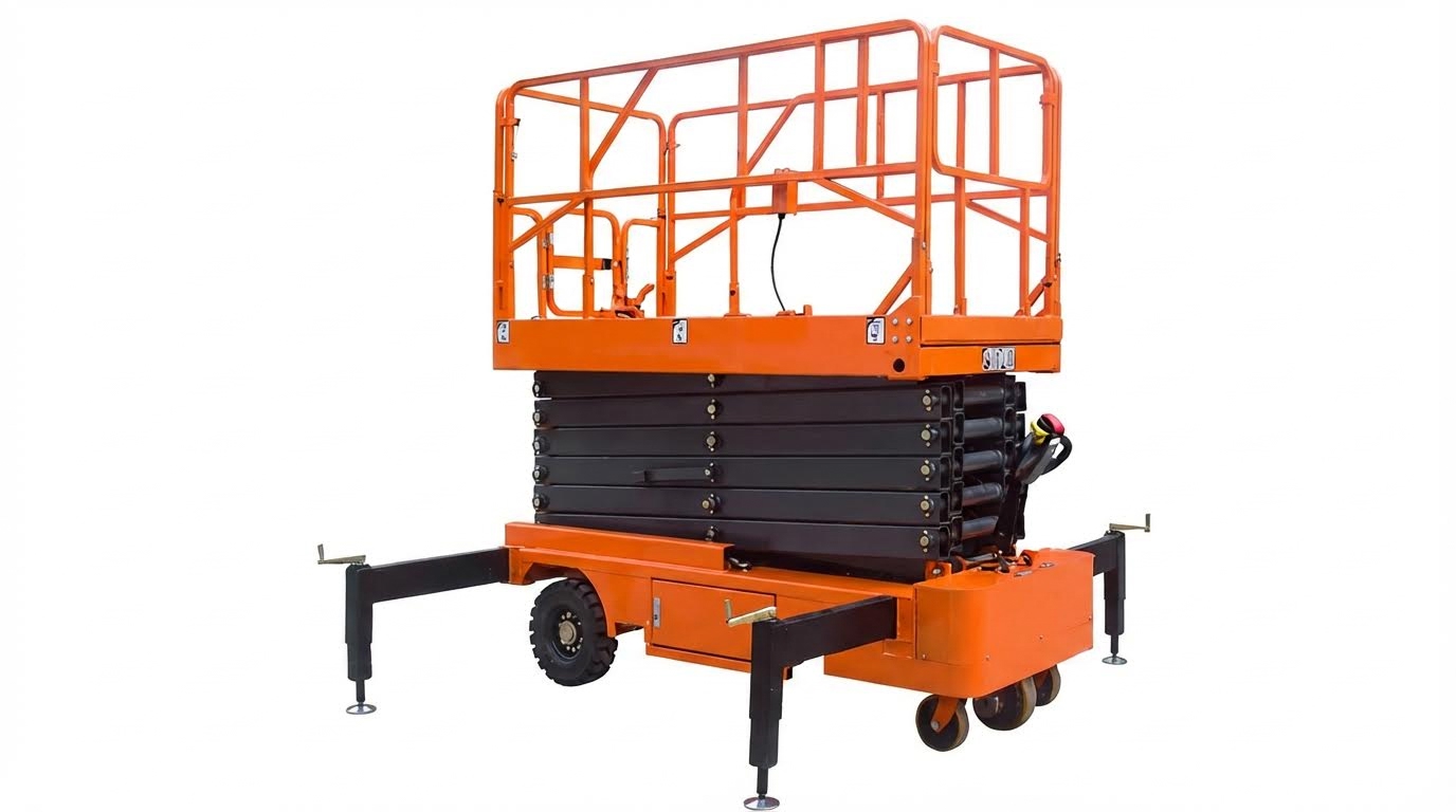
A typical unit consists of a guarded platform on top, a base frame on the ground, and several pairs of pantograph arms between them. Hydraulic cylinders or electric actuators sit between the base and the arms, while the power and control systems are usually housed in or on the base. Core elements include platform, base, pantograph arms, cylinders or actuators, and control systems.
| Component | Main Structural Role | Operational Impact / Best For… |
|---|---|---|
| Platform with guardrails | Supports people, tools, and materials; transfers load into top pivots | Large, stiff decks allow higher kg capacity and better working comfort without flex |
| Pantograph arms | Primary load‑bearing members in bending and compression | Arm thickness and steel grade govern rated capacity and fatigue life where FEA showed the need to increase wall thickness |
| Pins, rollers, guides | Carry shear and bearing loads at joints and sliding interfaces | High‑grade steels and proper diameters reduce wear and joint play, keeping the lift tight and stable over years |
| Base frame / chassis | Spreads all vertical and side loads into the floor or ground | Wide, stiff base improves resistance to tipping and allows higher working heights on the same footprint |
| Actuators (hydraulic / electric) | Apply driving force into the arms at a strategic point | Mounting geometry sets force range and stroke; must be matched to worst‑case load and arm angle |
Finite element analysis on real scissor lift structures showed that a minimum factor of safety of about 2.0 was required on main elements. To achieve this, engineers increased lever wall thickness from 2 mm to 3 mm and traction crossbar thickness from 3 mm to 3.2 mm, and specified higher‑grade steel (such as C20 / 1.0402) for rollers and guides. These changes significantly improved structural safety margins.
- Vertical load path: Platform → top arm pivots → arms in compression/bending → centre and lower pivots/rollers → base frame – this keeps loads symmetric and reduces torsion.
- Lateral stability: Wide base and cross‑bracing in arms – mitigate sway and side‑load risk, especially at full height.
- High capacity: Multiple X‑linkages share the load – allowing higher kg ratings and wider platforms than typical boom lifts while maintaining stability.
How structural design links to rated capacity
Rated capacity is not just about cylinder force. It is limited by arm section modulus, pin bearing stress, roller contact stress, and deflection at full height. That is why apparently small changes like 2 mm to 3 mm wall thickness or upgrading roller steel grade can unlock higher safe working loads without changing the overall geometry. FEA is routinely used to validate these margins.
💡 Field Engineer’s Note: When you see cracked arms or ovalised pin holes in the field, the root cause is often repeated overloads or side‑loading, not a single “big event.” Always compare site usage to the rated kg and intended duty cycle; the geometry is forgiving, but fatigue is not.
Power Systems, Controls, And Safety Logic
Power systems, control logic, and safety devices explain a big part of “how does scissor platform lift work” in real sites, because they turn pantograph mechanics into controlled, predictable motion. This section links hydraulic/electric drives, sensors, and structural safety into one coherent load-handling system.
Hydraulic vs. electric powertrains
Hydraulic and electric powertrains both convert motor power into linear force in the scissor arms, but they differ in load capacity, precision, noise, and best-fit environments. Understanding this trade-off is critical when you specify a lift for real duty cycles.
| Aspect | Hydraulic Scissor Lift | Electric Scissor Lift | Operational Impact / Best For… |
|---|---|---|---|
| Basic working principle | Motor-driven pump pressurizes hydraulic oil; pressure extends cylinder rod to push scissor arms apart (mechanism description). | Electric motor drives screw/gear/linear actuator, or a compact pump, to extend/retract the scissor mechanism (mechanism description). | Both answer “how does scissor platform work” at the powertrain level: motor torque becomes linear push in the X-linkages. |
| Typical load capacity | Can exceed 1,000 kg for industrial duty (heavy loads). | Commonly up to about 500 kg (lighter loads). | Hydraulic for heavy construction/industrial platforms; electric for light–medium indoor access. |
| Lifting speed | Generally slower; speed drops further in cold weather as oil viscosity increases (temperature effect). | Faster lift speeds with precise control of 0.1–0.5 m/s via motor control (speed regulation). | Electric suits high-cycle warehouse and maintenance work where time per lift matters. |
| Noise level | Around 70 dB during operation, due to pump and engine noise (noise data). | Typically under 50 dB (low noise). | Electric is preferred for hospitals, schools, and occupied offices. |
| Control precision | Platform positioning via valve throttling is relatively coarse (valve control). | Programmable systems can hold ±1 mm platform accuracy (high precision). | Electric fits assembly, alignment, and picking tasks where millimetre accuracy saves rework. |
| Environment suitability | Performs well outdoors, on rougher ground, and where grid power is unreliable (outdoor use). | Best on flat indoor floors with high cleanliness requirements and good charging infrastructure (indoor use). | Hydraulic for construction yards; electric for warehouses, food, pharma, and cleanrooms. |
| Maintenance profile | Requires oil analysis, filter changes, leak checks, and hose inspections (maintenance). | Lower routine maintenance; no hydraulic oil, fewer leak paths (maintenance). | Electric reduces downtime where maintenance windows are tight. |
| Energy & emissions | Engine-driven units emit exhaust and often consume more energy over time (emissions). | Lower energy use and zero point-of-use emissions (energy saving). | Electric helps meet ESG targets and indoor air-quality rules. |
- Hydraulic cylinder sizing: Must handle peak actuating forces up to about 6.5 kN for a 100 kg, 1 m lift so the system stays within pressure limits across the stroke (force data).
- Electric motor selection: Uses AC or permanent-magnet motors with vector control to cut energy use by about 30% which reduces heat and battery size (efficiency gain).
- Service life: Brushless electric motors can extend service life from roughly 2,000 to 10,000 hours cutting replacement cost and downtime (brushless upgrade).
💡 Field Engineer’s Note: In cold yards below 0°C, hydraulic scissor lifts often “wake up” sluggishly because oil thickens. If you must run hydraulic outdoors in winter, specify low-temperature fluid and allow warm-up cycles in your method statements.
How the powertrain fits into “how does scissor lift work”
Mechanically, both powertrains only do one job: push or pull a single actuator that changes the angle of the X-arms. The pantograph geometry multiplies this actuator force into vertical lift, which is why the same 1–7 kN actuator range can safely raise a 100 kg payload over 1 m when the arms and pivots are correctly sized and braced (force range).
Motion control, sensors, and closed-loop logic
Modern scissor lifts work through a closed-loop control system that reads sensors, drives the motor or pump, and constantly corrects motion for comfort and safety. This is the “nervous system” that turns raw power into smooth, predictable platform travel.
The electrical control architecture is usually modular with four units: Control Unit, Power Unit, Sensing Unit, and Human–Machine Interaction Unit. Together they form a closed loop that measures load and position, then adjusts motor torque and speed in real time.
| Subsystem | Key Elements / Typical Performance | Operational Impact | |||||||||||||||||||||||||||||||||||||||||||||||||||||||||||||
|---|---|---|---|---|---|---|---|---|---|---|---|---|---|---|---|---|---|---|---|---|---|---|---|---|---|---|---|---|---|---|---|---|---|---|---|---|---|---|---|---|---|---|---|---|---|---|---|---|---|---|---|---|---|---|---|---|---|---|---|---|---|---|---|
| Control Unit | PLC or dedicated control motherboard with millisecond-level command processing (architecture). | Executes lift/lower commands, reads sensors, and enforces interlocks so operators cannot override safety logic. | |||||||||||||||||||||||||||||||||||||||||||||||||||||||||||||
| Power Unit | AC asynchronous or permanent-magnet motors with vector control and variable-frequency drives enabling 0.1–0.5 m/s stepless speed control (speed range). | Allows soft starts and stops, reducing platform sway and improving comfort for personnel and fragile loads. | |||||||||||||||||||||||||||||||||||||||||||||||||||||||||||||
| Sensing Unit – load | Weight sensors with ±1%FS accuracy up to about 2,000 kg (load sensors). | Detects overload before lift starts or during motion, preventing structural overstress and instability. | |||||||||||||||||||||||||||||||||||||||||||||||||||||||||||||
| Sensing Unit – position | Mechanical limit switches with stroke error ≤2 mm at upper and lower limits (limit accuracy). | Guarantees the platform stops before hitting hard mechanical stops, reducing impact loads into the structure. | |||||||||||||||||||||||||||||||||||||||||||||||||||||||||||||
| Human–Machine Interaction | Waterproof button boxes, emergency stop switches, indicator lights, and sometimes LCD displays that cut misoperation by about 40% (HMI data). | Clear feedback on load and height reduces operator error, which is a major root cause of incidents. | |||||||||||||||||||||||||||||||||||||||||||||||||||||||||||||
| Closed-loop motion profile | Example: 10 m platform controlled to reach 0.3 m/s in about 1.5 s under full load, adjusting acceleration slope by load feedback Matching Scissor Lift Design To Applications Scissor lift design must match environment, load, and duty cycle so the mechanism, power system, and controls work safely and efficiently over the machine’s full life. This is the real answer to “how does scissor lift work” in the field.
Indoor vs. outdoor and terrain considerationsIndoor and outdoor scissor lifts use the same X‑link mechanism, but flooring, wind, emissions, and terrain dictate very different power systems and chassis designs.
How indoor/outdoor conditions affect “how does scissor lift work”The core scissor mechanism always converts actuator force into vertical lift through the X‑pattern arms mechanism description. Indoors, smooth floors and no wind mean the limiting factor is usually load and platform size. Outdoors, wind, gradients, and surface compliance add side loads into the structure, so the same mechanism needs wider chassis, pothole protection, and stricter operating envelopes. Capacity, duty cycle, and TCO-driven selectionCapacity, duty cycle, and total cost of ownership (TCO) define which scissor lift design is economical over thousands of operating hours, not just on day one.
How capacity and duty cycle change how a scissor lift works internallyAs capacity and lift height rise, the actuating force through the cylinders increases non‑linearly, which means higher peak kN loads on pins and welds force analysis. High duty cycles add thermal loading to motors and pumps. In response, designers upgrade steel thicknesses, choose higher‑grade materials, and use smarter electrical controls with trapezoidal motion profiles to keep the ride smooth and reduce impact loads on every start and stop.
Final Engineering Takeaways For SpecifiersScissor lifts work safely only when geometry, structure, power, and controls are treated as one integrated system. The pantograph multiplies actuator force into vertical lift, but it also creates high loads at low height. Engineers must size cylinders, arms, and pins for these worst‑case forces, not for mid‑stroke conditions. A clear vertical load path through stiff arms, quality pins, and a wide base protects against bending, torsion, and fatigue. Finite element checks and a safety factor near 2.0 on main parts turn this theory into real structural life. Closed‑loop controls, load sensors, and limit switches then keep motion inside this safe envelope on every cycle. Powertrain choice must follow the job. Hydraulic units suit heavy outdoor loads and rough terrain. Electric units suit clean, high‑cycle indoor work with strict noise and emission limits. Matching capacity, duty cycle, and environment cuts downtime and total cost per metre lifted. The practical takeaway for engineering and operations teams is simple. Start with the site and duty cycle. Select geometry, structure, and powertrain that hold margin at the worst case, then insist on modern sensing and control. Partners like Atomoving can help turn these rules into a safe, efficient platform specification. Frequently Asked QuestionsHow does a scissor lift work?A scissor lift operates using a hydraulic or electric system to move its platform vertically. Typically, one to three hydraulic cylinders power the scissor legs to move upwards or downwards. The power source provides the energy for this process, and a platform at the top is connected to the scissor legs, carrying the load. Hydraulic Scissor Lift Guide. What is the mechanism of a scissor lift?The mechanism of a scissor lift involves hydraulic or electric power systems that push the scissor legs to extend vertically. This movement is facilitated by a motor that drives the hydraulic fluid into cylinders, causing them to expand or contract. A platform at the top moves accordingly, allowing the lift to raise or lower loads efficiently. Scissor Lift Mechanics. |