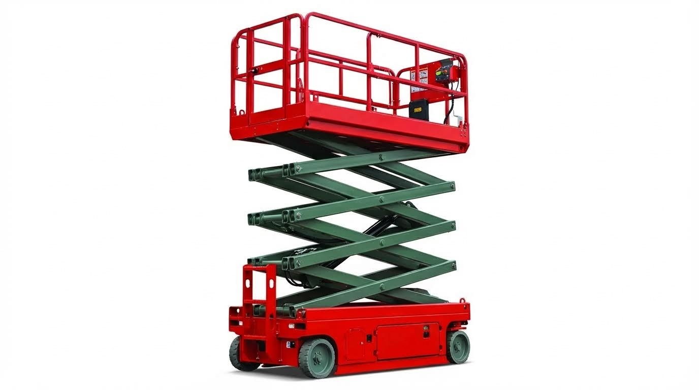
Scissor lift capacity tells you exactly how much weight you can safely put on the platform, including people, tools, and materials. This guide explains how much can a scissor lift lift in real-world conditions, why the rating is lower than the true structural limit, and how engineering, standards, and inspections keep you inside a safe working envelope.
Understanding Scissor Lift Capacity Basics
Scissor lift capacity basics explain how much a scissor platform can safely lift by defining rated platform capacity, built‑in safety margins, and the difference between structural strength and the number printed on the data plate. If you want to know how much can a scissor lift lift in real work, you must understand these fundamentals, not just the headline kilogram figure.
- Rated capacity is a safety-limited number: It is always lower than the true structural limit – this protects against dynamic loads, misuse, and real-world uncertainties.
- All weight on the platform counts: People, tools, and materials are included – you size the job to total load, not just the heaviest item.
- Standards force large safety factors: Structures and hydraulics are tested well above rating – the label capacity is a conservative working limit, not a breaking point.
- Capacity can vary with height and setup: Some models derate at full extension or outdoors – you must read the capacity chart, not assume “one number fits all.”
💡 Field Engineer’s Note: When planning jobs, I assume a practical working load of about 70% of the nameplate capacity to leave margin for extra tools, heavier PPE, and small errors in weight estimates.
Rated platform capacity vs. structural limits
Rated platform capacity is the safe working load printed on the lift, while structural limits are the higher loads the machine can survive in testing before failure or instability. The gap between them is your built‑in safety margin.
Engineering calculations and tests determine the maximum load the structure, pins, welds, and cylinders can carry before yielding or losing stability. Designers then divide that theoretical maximum by a safety factor, typically about 1.5–3, to set the rated platform capacity. For example, a unit structurally capable of around 900 kg might receive a rated capacity of only about 450–600 kg to keep operation within safe elastic limits and stability margins. Engineering guidance on scissor lift design explains how these margins arise from structural and stability analysis.
| Concept | Typical Level | What It Includes | Operational Impact |
|---|---|---|---|
| Structural limit | 100% theoretical capacity | Maximum load from calculations and test before yielding or instability | Never used in the field; only for engineering and certification tests |
| Required safety factor | 1.5–3× on structure | Accounts for material scatter, weld quality, fatigue, and dynamic effects | Ensures the lift survives shock loads and abuse without failure |
| Rated platform capacity | ≈50–75% of structural limit | Total allowed load: people + tools + materials | This is the “how much can a scissor lift lift” number you must obey |
| Test load in certification | Often ≥1.25–4× rated load | Overload tests on structure and stability per standards | Verifies the machine safely exceeds rated capacity under controlled tests |
Regulations require that aerial platforms physically support several times their rated load in tests. For example, some rules demand the structure support at least four times the rated load, while safe working loads stay at about 75% of the maximum load-carrying capacity found in structural calculations and testing. Design guidance also notes that dynamic effects from moving or shifting loads can multiply forces, which is another reason the rated capacity stays well below the true limit.
- Rated platform capacity: Maximum total live load allowed in normal use – this is the only number operators should use.
- Structural limit: Calculated and tested maximum before damage or tip – kept in the background as an engineering reserve.
- Dynamic factors: Braking, impact, and shifting loads – justify why rated capacity is conservative compared with static strength.
- Inspection and testing: Regular load testing and checks – confirm the lift still meets its original rated capacity over time.
How to think about “headroom” between rating and failure
In practice, you should treat the rated capacity as a hard ceiling, not a target to exceed “because there is safety factor.” The hidden headroom exists to absorb unknowns: mis-weighed materials, slightly bent arms, pressure spikes in hydraulics, or a worker stepping hard onto the platform. Using that headroom intentionally is how lifts get damaged or tip.
💡 Field Engineer’s Note: If a task routinely pushes a lift above 80–85% of its rated platform capacity, I specify the next larger model; repeated high loading accelerates fatigue in pins, welds, and cylinder mounts.
How standards and safety factors set the rating

Standards and safety factors set scissor lift ratings by forcing designers to keep the rated load well below what the structure and hydraulics can actually withstand. This codified gap is what keeps “how much can a scissor lift lift” safely predictable across different models.
Regulatory and consensus standards require aerial platforms to support multiples of the rated load under controlled test conditions. Guidance notes that regulations such as OSHA require platforms to support at least four times their rated load, while ANSI and ASME standards restrict safe working loads to roughly 75% of the maximum capacity established by structural calculations and testing. Engineering references describe typical safety factors in the 1.5–3 range on structural elements and higher overall factors when you include stability and dynamic test requirements.
| Design / Standard Element | Typical Requirement or Range | What It Controls | Best For… |
|---|---|---|---|
| Structural safety factor | ≈1.5–3× | Strength of arms, pins, welds under maximum load | Ensuring steel stays in elastic range under real loads |
| Test load vs. rated load | Up to ≥4× rated | Proof that structure and platform can withstand overload | Certification and periodic proof testing |
| Working load vs. theoretical maximum | ≈≤75% | Margin for dynamic loads and material variability | Setting conservative nameplate capacity |
| Stability factor against overturning | ≈1.33 or higher | Tip resistance under worst-case loading | Working safely with people, tools, and wind loads |
OSHA guidance also makes it clear that employers must keep the platform load within the manufacturer’s rating at all times; exceeding that label violates both the standard and the engineering assumptions behind the safety factors. OSHA’s scissor lift resource emphasizes that the rated platform capacity is the legal and safe limit for the total load on the platform.
- Codes drive the math: OSHA, ANSI, and similar standards define minimum test factors – engineers cannot “shave” safety margins for extra kilograms on the label.
- Dynamic and wind loads are baked in: Test procedures include movement and disturbance – capacity already accounts for real-world motion.
- Rated load is a compliance value: Employers must enforce it – overloading is both a safety risk and a regulatory violation.
- Inspection maintains the margin: Annual tests check the lift still meets its rated platform capacity – corrosion or damage must be repaired or the unit derated.
💡 Field Engineer’s Note: When I audit fleets, any lift with unknown repair history or visible structural damage is treated as derated to 0 kg until it passes a formal load test against its original standard-based rating.
Engineering Factors That Define Safe Load Limits
Engineering factors like scissor geometry, hydraulics, and stability ultimately decide how much can a scissor platform lift safely at any given height and position. Rated capacity is a conservative limit below structural and tipping thresholds.
- Scissor geometry: Arm angle and linkage layout change mechanical advantage with height – capacity at ground is not the same as capacity at full stroke.
- Hydraulics: Cylinder bore and system pressure cap the usable force – pressure limits often govern high‑reach capacity.
- Stability: Centre of gravity must stay inside the wheel/outrigger footprint – this stops tip‑over before steel or hydraulics actually fail.
- Safety factors: Standards require big margins between failure and rating – so the real “break point” is far above the nameplate load.
💡 Field Engineer’s Note: When you see a lift derated at maximum height, it is rarely “weak steel.” It is usually the combination of poor mechanical advantage and stability margins shrinking as the centre of gravity climbs.
Scissor geometry and mechanical advantage
Scissor geometry controls the mechanical advantage between cylinder force and platform load, so arm angle directly affects how much can a scissor platform lift lift at different heights. At low height the linkage is efficient; near full extension it becomes force‑hungry.
The key geometric variables are: arm length, arm angle to the base, and the horizontal distance from the base pivot to the cylinder attachment. These define the mechanical advantage (MA) curve along the stroke. As the arms open and become flatter, MA drops, so the same load demands higher cylinder force. This is why a mechanism that is structurally strong enough for 900 kg may only be rated for 450–600 kg after applying safety factors and worst‑case geometry. Design calculations show typical safety factors between 1.5 and 3 on structural capacity.
| Geometry Condition | Arm Angle vs Base | Mechanical Advantage | Practical Effect on Capacity | Operational Impact |
|---|---|---|---|---|
| Platform near stowed | Steep (arms closer to vertical) | High – cylinder force is efficiently converted to lift | Hydraulics and structure are well within limits | Plenty of margin; lift feels “strong” and responsive |
| Mid‑stroke | Moderate angle | Medium – typical design point | Rated capacity usually based on this plus safety factors | Normal working zone for repeated cycles |
| Near full extension | Flat (arms closer to horizontal) | Low – huge cylinder force needed for same load | Capacity may be derated at max height | Respect any “at height” derating in the manual |
- Longer arms: Increase reach and height – but amplify bending and buckling loads that must be checked in design.
- Actuator further from pivot: Improves MA at some positions – yet can worsen it at others, so engineers optimise the full stroke.
- Multiple scissor stages: Allow higher platforms – but stack tolerances and deflections, so stiffness and weld quality matter more.
Why capacity can change with height
Because MA falls as the arms flatten, the cylinder pressure required to lift a given platform load rises. At some point, either the hydraulic pressure limit or the stability requirement is reached. Manufacturers may therefore publish a single conservative platform rating that covers all heights, or specify a lower capacity at maximum elevation.
Hydraulic pressure, cylinders, and derating at height
The hydraulic system sets the maximum usable force in the scissor linkage, so cylinder bore and system pressure directly bound how much can a aerial platform lift before hitting pressure or component limits. Geometry then decides where along the stroke this limit bites.
The cylinder must generate enough force at the worst‑case geometry, typically near full extension where MA is lowest. System pressure ratings include margin above working demand to avoid hose, tube, or seal failure. Design guidance shows hydraulic limits interacting with geometry so that a cylinder that is comfortable at low height may operate near its pressure ceiling at full elevation.
| Hydraulic Factor | Typical Engineering Intent | Effect on Safe Load | Operational Impact |
|---|---|---|---|
| Cylinder bore diameter | Set to deliver required force at rated pressure | Larger bore = higher potential capacity, but slower speed | Heavier lifts may raise more slowly but stay within safe pressure |
| System pressure rating | Chosen with margin vs. burst/working limits | Higher rating allows more force, but hoses and seals must match | Overloading can push pressure near relief valve setting |
| Relief valve setting | Protects components from overload pressure | Caps maximum lifting force regardless of load placed | Platform may refuse to rise if overloaded, even if structure is strong |
| Oil temperature and viscosity | Kept within design band | Very cold oil slows response; hot oil can reduce efficiency | In cold storage, lifts can feel weak or “stuck” until oil warms |
Dynamic loads also matter. Starting, stopping, or shifting materials can transiently push hydraulic forces above static levels. Test standards therefore required structures to withstand several times the rated capacity, while keeping working loads to roughly 75% of the theoretical maximum.
- Derating at height: When MA is poor and pressure is high, manufacturers may specify a lower platform capacity at or near maximum height – this prevents running continuously at the hydraulic limit.
- Maintenance impact: Contaminated or low oil, damaged hoses, or worn seals all reduce effective capacity – the lift may stall earlier or creep down under load.
💡 Field Engineer’s Note: If a lift “won’t go up” only when it is nearly fully extended, suspect a pressure‑limited system at poor geometry, not a weak battery. Measuring pressure at the cylinder port under a known test load quickly confirms this.
Stability, support polygon, and wind loading
Stability criteria ensure the combined centre of gravity of machine and load stays inside the support polygon, so tip‑over limits often answer how much can a order picking machines lift before structural strength is even approached. Wind and ground conditions can reduce this margin.
The support polygon is the footprint formed by wheels or outriggers. As the platform rises, the centre of gravity climbs and can shift sideways with any off‑centre load. Stability calculations typically require a minimum factor of about 1.33 against overturning, meaning the restoring moment must be at least one‑third greater than the tipping moment. This is separate from structural or hydraulic strength.
| Stability Factor | Typical Requirement | What It Controls | Operational Impact |
|---|---|---|---|
| Against overturning | ≥ 1.33 in many design guides | Margin before the centre of gravity crosses the edge of the footprint | Prevents tip‑over when loaded to rated capacity on level ground |
| Structural safety factor | ≈ 1.5–3 on members and joints | Margin before steel yields or buckles | Ensures structure survives test loads above rating |
| OSHA support margin | Supports ≥ 4× rated load | Overall platform and support strength | Real failure load is well above the nameplate load |
External conditions can erode stability margins quickly. For outdoor‑rated units, OSHA guidance notes that typical scissor lifts are limited to wind speeds below about 28 mph (≈12.5 m/s). Higher gusts add overturning moment and can cause collapse, especially at full height. Soft or sloped ground also changes the effective support polygon and can shift the tipping line closer to the centre of gravity.
- Uneven load distribution: Concentrating heavy materials on one side of the platform shifts the centre of gravity – tipping risk can rise even if total weight is within the rated kg.
- Ground quality: Using a lift on soft, sloped, or debris‑covered surfaces reduces stability – wheels can sink or roll unexpectedly, shrinking the safe envelope.
- Movement at height: Driving or slewing with the platform elevated (if allowed at all) adds dynamic overturning moments – this is why many manuals ban travel above a set height.
How standards tie stability into capacity
Design and test standards require that when the lift carries its rated platform load, with specified horizontal offsets and simulated wind, the combined centre of gravity must remain within the support polygon with the mandated stability factor. Only after the design passes these tests do manufacturers publish a rated capacity, which is therefore a stability‑checked, hydraulically‑checked, and structurally‑checked number.
💡 Field Engineer’s Note: In real jobs, tip‑overs almost always involve a combination of factors: near‑max height, side‑loaded materials, wind, and poor ground. Staying well under rated load when any one of these is marginal buys a lot of safety margin.
Specifying And Managing Capacity In Real Operations
In real jobs, “how much can a scissor platform lift” depends on task, height, environment, and how you manage loading, not just the brochure number. This section turns the theoretical capacity into day‑to‑day rules you can actually apply.
- Always start from the data plate: Use only the rated platform capacity – this already includes safety factors and test margins. OSHA requires you never exceed this rating.
- Think in total load, not just people: Add body weight, tools, and materials – the sum must stay at or below the rated kg. Design calculations assume total platform load.
- Respect derating at height: Some models reduce allowable load near maximum height – this protects against geometry and stability limits at full extension. Mechanical advantage drops at full height.
- Match lift to the surface and wind: Use only on firm, level ground and within wind limits – ground or wind issues can overturn a lift that is “within weight.” OSHA highlights surface and wind as key stability factors.
- Back everything with inspection and training: Regular inspections and operator training keep the rated capacity valid – damaged structures or untrained use destroy the safety margin. Manuals specify maintenance and training requirements.
💡 Field Engineer’s Note: When planning work, I assume a practical working load of about 80–90% of the nameplate rating to absorb tool swaps, extra materials, and dynamic bumps. If you routinely run at 100%, you are one mistake away from overload.
Matching capacity to task, height, and environment
To answer “how much can a scissor platform lift lift” for a specific job, you must combine rated capacity, platform height, and site conditions into one plan.
Typical electric and diesel scissor lifts list platform capacities roughly in the 250–680 kg range and working heights around 5–16 m. Manufacturer manuals show capacity and height limits together. Your job is to choose a model where the real load and conditions sit comfortably inside those limits.
| Typical Task Scenario | People + Tools + Material (Example) | Recommended Rated Capacity Band | Height Range | Operational Impact / Best For… |
|---|---|---|---|---|
| Light inspection, sensors, cameras | 1 person (90 kg) + 20 kg tools ≈ 110 kg | ≥ 250 kg | 5–8 m | Small indoor units; plenty of spare margin for extra tools. |
| Ceiling MEP work, light ducting | 2 people (180 kg) + 80 kg tools/materials ≈ 260 kg | 350–450 kg | 8–12 m | Standard indoor construction work with modest materials on deck. |
| Heavy mechanical install, cable trays | 2 people (180 kg) + 200 kg materials ≈ 380 kg | 450–600 kg | 8–14 m | Heavier trade work; need higher capacity plus tool carts. |
| Facade work, cladding bundles | 2 people (180 kg) + 350 kg materials ≈ 530 kg | 600–680 kg | 10–16 m | High loads near outdoor height limits; careful wind and ground checks needed. |
These bands are indicative, not design data. Always compare your real calculated load with the specific model’s rating and any derating notes in the manual. Structural and hydraulic design calculations already include safety factors, so you must not “add your own” by overloading.
- Indoor vs outdoor: Choose lower capacity margins outdoors because wind and uneven ground consume stability reserve – even a properly loaded lift can tip in high wind. Outdoor-rated units are limited to specific wind speeds.
- Height effect: If the manual shows different capacities at different heights, always plan for the lowest listed capacity – near full height, mechanical advantage and stability are worst.
- Surface quality: On marginal slabs or mezzanines, check that the floor can support total machine weight plus load – capacity labels assume a firm, level surface. OSHA stresses firm, level surfaces for stability.
- Task duration and turnover: For jobs with frequent material changeovers, choose a higher capacity band – this reduces the temptation to “just add one more box.”
How to quickly estimate if a lift is big enough
1) Add up people, tools, and material weight in kg. 2) Multiply by about 1.1 to allow for small extras. 3) Choose a lift whose rated platform capacity is at least that number and still meets the required height. If you are within 10% of the rating, move up a size rather than running at the limit.
Load distribution, dynamic effects, and overloading risks
Even when the total weight is within the rating, bad load distribution and dynamic effects can still cause structural damage or tip‑over.
The platform rating assumes the combined centre of gravity stays within the support polygon formed by the wheels or outriggers. Uneven loading narrows the tipping margin. Design standards require a minimum stability factor against overturning.
| Load / Motion Condition | What Happens Physically | Risk Created | Operational Control |
|---|---|---|---|
| Stacking material on one side rail | Centre of gravity shifts sideways towards platform edge. | Reduced lateral stability, higher tip risk when driving or in wind. | Keep heavy items central and low; use both sides symmetrically. |
| Tall, top‑heavy pallets or duct sections | Overall centre of gravity rises; sway increases. | Greater overturning moment under wind or sudden stops. | Secure tall loads; reduce height or capacity; consider another handling method. |
| Driving or braking with load elevated | Inertia adds dynamic forces beyond static weight. | Momentary loads can exceed structural and stability design. | Only travel at low height unless the manual explicitly allows elevated travel. |
| Sudden loading (dropping materials) | Impact multiplies apparent load through acceleration. | Local platform damage, pin or weld fatigue. | Place loads gently; avoid throwing or dropping items onto the deck. |
| Wind gusts on outdoor work | Lateral force acts at platform height. | Large overturning moment, especially at full extension. | Stay within rated wind speed and reduce height or load as wind increases. |
Dynamic test requirements mean the structure can withstand several times the rated capacity under controlled conditions, but the working capacity is intentionally limited to about 75% of the theoretical maximum. Safety factors of roughly 1.5–3 are built into the rating. You do not “own” that extra margin in daily work; it exists to cover dynamic and unforeseen effects.
- Respect load‑sensing systems: Modern lifts use sensors that cut movement when overload is detected. Do not bypass or “fool” these systems with counterweights or people jumping off. Calibration procedures ensure overload alarms trigger near rated capacity.
- Follow inspection intervals: Daily checks plus deeper monthly and annual inspections keep the structure and hydraulics capable of their original rating – cracked welds or bent arms silently reduce real capacity. Formal load testing verifies rated platform capacity annually.
- Train operators on weight awareness: Operators should estimate weights in kg, read capacity plates, and recognise when loads are becoming top‑heavy – this is a core part of required training. OSHA requires training on handling materials within weight limits.
Practical overloading red flags to watch for
Watch for these signs and stop immediately if you see them: 1) Platform struggles or stalls when raising. 2) Overload alarm or warning lights. 3) Noticeable flexing or creaking of the deck or guardrails. 4) Lift feels unusually “soft” or wobbly at height. These are early warnings that you are at or beyond safe capacity, even if the calculated weight seems acceptable.
Final Thoughts On Safely Using Scissor Lift Capacity
Safe scissor lift capacity comes from three things working together: structural strength, hydraulic limits, and stability margins. Engineers design the arms, pins, and platform to carry far more than the rated load, then apply safety factors and standards to set a lower, predictable capacity. Hydraulics, geometry, and height decide how close you can get to that capacity at each position without hitting pressure or buckling limits.
Stability then closes the loop. The machine must keep its centre of gravity inside the support polygon with rated load, side offsets, and wind. Ground quality, wind, and load position can eat into this margin even when weight stays below the nameplate figure.
Operations teams should treat the data plate as a hard ceiling and plan work at a comfortable percentage below it. Match the lift to task, height, and environment, and reduce load when ground, wind, or load shape are less than ideal. Keep heavy items low and central, avoid travel at height, and never bypass overload or safety systems.
With correct specification, disciplined loading, and regular inspection, Atomoving scissor platforms will operate inside their engineered envelope and deliver safe, reliable elevation for years.
Frequently Asked Questions
How much can a scissor lift carry?
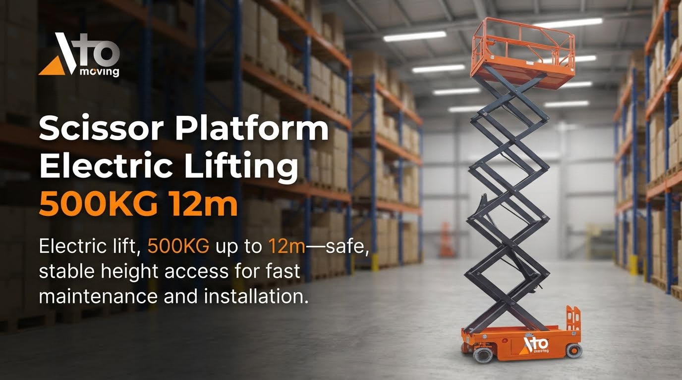
A scissor lift’s carrying capacity depends on its size and type. For example, smaller electric models like a 19-foot lift can typically carry up to 500 kg, while larger diesel-powered lifts may handle up to 680 kg at heights of around 25 meters. Scissor Lift Types. Always check the manufacturer’s load chart for precise details.
What happens if a scissor lift is overloaded?
Overloading a scissor lift can lead to serious issues such as damage to components like cables, pulleys, and motors. In extreme cases, this could cause catastrophic failures, risking both equipment and operator safety. To avoid these problems, never exceed the recommended weight limit specified by the manufacturer. Lift Weight Limits.

